
Determination method, determination apparatus, and recording medium

a technology of determination apparatus and recording medium, which is applied in the direction of optical radiation measurement, instruments, spectrometry/spectrophotometry/monochromators, etc., can solve the problems of not being able to observe the time-series changes of determined cells or to culture determined cells, and achieve the effect of determining the cell type more accurately and excellent

Active Publication Date: 2021-05-13
HORIBA LTD
View PDF0 Cites 0 Cited by
  • Summary
  • Abstract
  • Description
  • Claims
  • Application Information

AI Technical Summary

Benefits of technology

The present invention allows for quick and accurate measurement of the characteristics of an entire cell by emitting excitation light to the entire cell and measuring the scattered light. This is done without being affected by the detailed structure of the cell. By comparing the overall characteristics of the measured spectrum, the cell type can be determined more accurately than before.

Problems solved by technology

In the case of using a method of staining cells or a method of destroying cells, it is not possible to observe the time-series changes of determined cells or to culture the determined cells.

Method used


Image

  • Determination method, determination apparatus, and recording medium
  • Determination method, determination apparatus, and recording medium
  • Determination method, determination apparatus, and recording medium

Examples


first embodiment

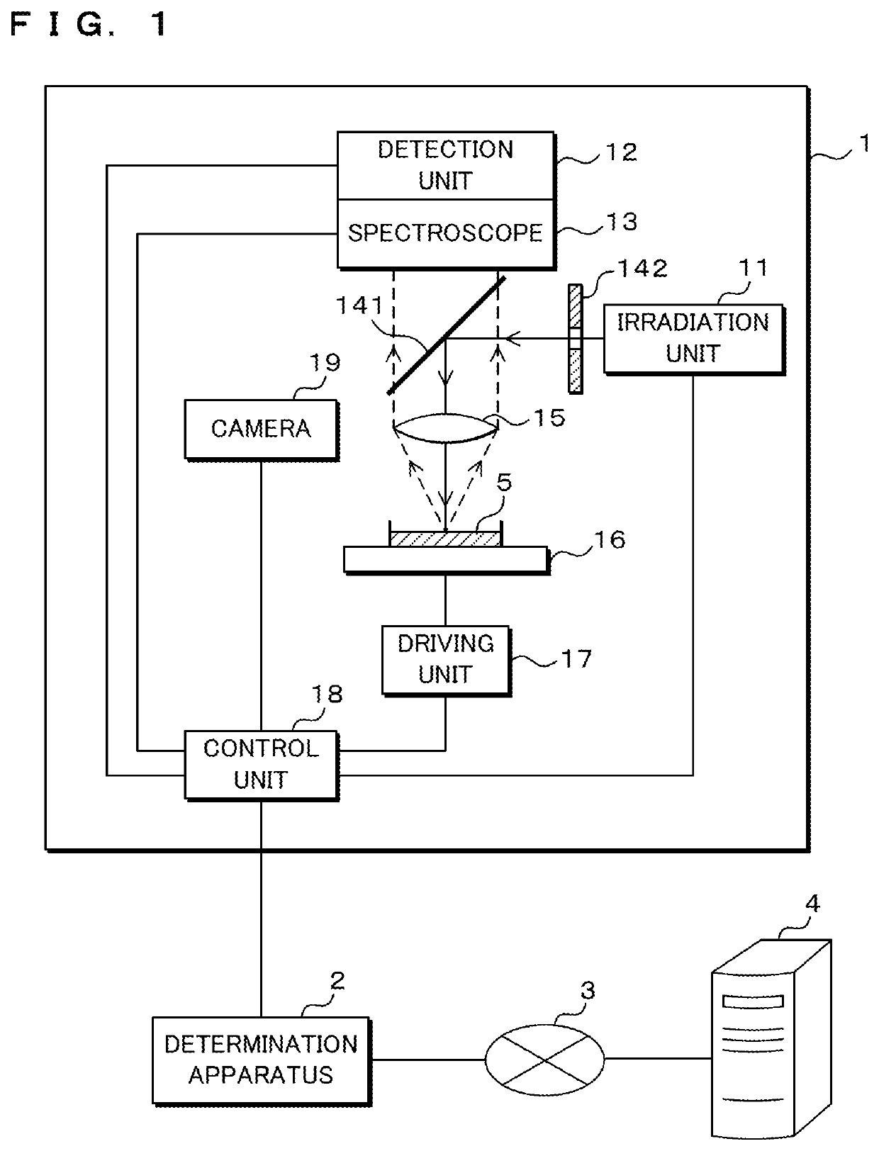
[0044]FIG. 1 is a block diagram illustrating the configuration of a Raman scattered light measuring apparatus 1. The Raman scattered light measuring apparatus 1 includes a sample holding unit 16 for holding a sample 5, an irradiation unit 11 for emitting laser light, a mask 142, a beam splitter 141, and a lens 15. For example, the sample 5 is in a liquid state and stored in a container such as a petri dish. The sample holding unit 16 is, for example, a sample table on which a container containing the sample 5 is placed. The sample holding unit 16 may be in a form other than the sample stage. The laser light emitted from the irradiation unit 11 is focused into thin light by the mask 142, reflected by the beam splitter 141, passes through the lens 15, and is irradiated to the sample 5. The irradiation unit 11, the mask 142, the beam splitter 141, and the lens 15 are disposed so that the laser light passes only through the optical axis and the vicinity of the optical axis in the lens 1...

second embodiment

[0079]In a second embodiment, a form in which cell determination is performed using a part of the Raman spectrum is shown. The Raman spectrum of a cell includes a portion, which reflects the characteristics of the cell relatively strongly and in which a change depending on the cell type is large, and includes a portion, which does not reflect the characteristics of the cell much and in which a change depending on the cell type is small. Hereinafter, a portion that strongly reflects the characteristics of the cell in the Raman spectrum of the cell is referred to as a fingerprint region. In the second embodiment, cell determination is performed using the fingerprint region.

[0080]FIG. 13 is a graph showing an example of a fingerprint region in the Raman spectra. The Raman spectra shown in FIG. 13 are the same as the Raman spectra shown in FIG. 4. The range of the fingerprint region is a range in which the Raman shift is 1250 to 1750 cm−1. The fingerprint region reflects important infor...


PUM

PropertyMeasurementUnit
Raman shiftaaaaaaaaaa
Raman spectrumaaaaaaaaaa
Raman spectraaaaaaaaaaa

Abstract

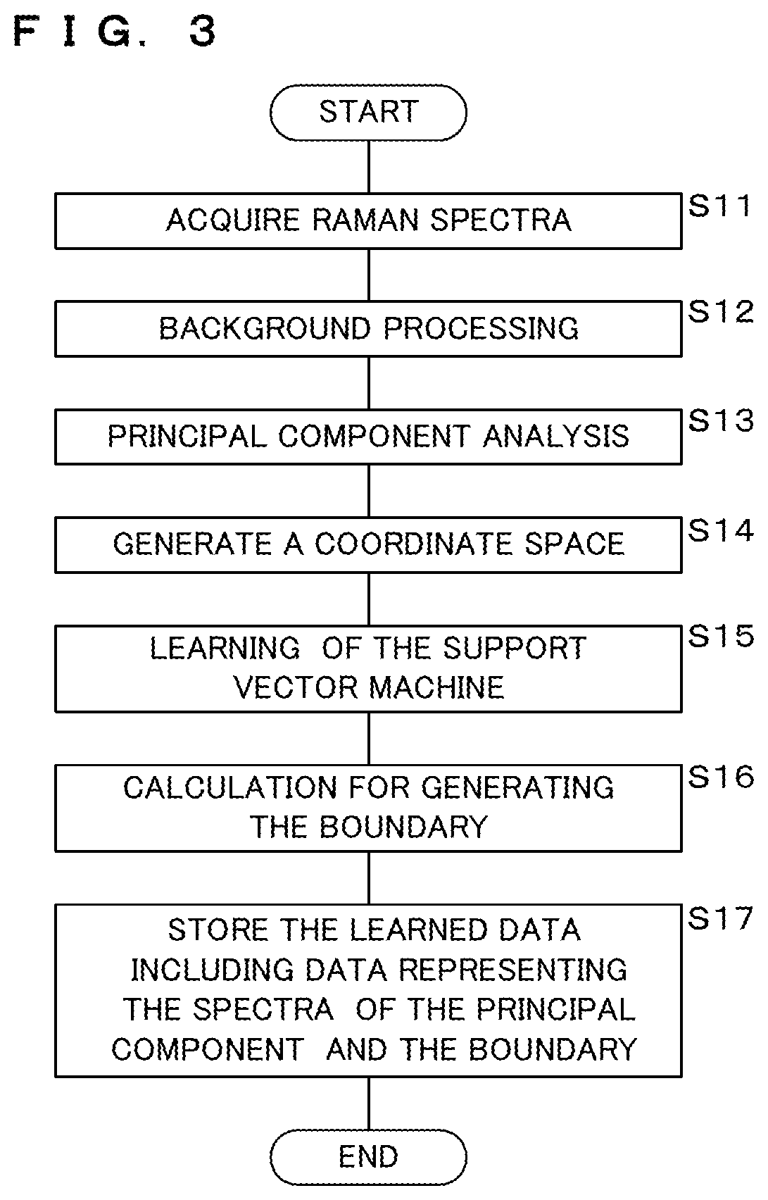
In a method of determining the type of each cell contained in a sample, one Raman spectrum is acquired from one undetermined cell, a plurality of degrees of matching of a Raman spectrum of the undetermined cell with respect to spectra of a plurality of principal components obtained by principal component analysis of a plurality of Raman spectra that are obtained one by one from each of a plurality of known types of cells are calculated, and a type of the undetermined cell is determined by classifying the plurality of degrees of matching based on a result obtained by classifying a plurality of principal component scores corresponding to each of the plurality of known types of cells obtained by the principal component analysis depending on the type of cells by a learning model using supervised learning.

Description

TECHNICAL FIELD[0001]The present invention relates to a determination method, a learning method, a determination apparatus, and a computer program for determining a cell type based on a Raman spectrum.BACKGROUND ART[0002]In the field of regenerative medicine, it is necessary to examine whether or not cultured cells have differentiated into desired types of cells. In the field of medical diagnosis, it is sometimes necessary to determine whether or not cells collected from a patient are normal types of cells. Thus, a method for determining the type of each cell derived from an organism is required. In the case of using a method of staining cells or a method of destroying cells, it is not possible to observe the time-series changes of determined cells or to culture the determined cells. For this reason, it is desirable that the method of determining the cell type is a non-destructive and non-invasive method. As such a method, there is a method using Raman spectroscopy. Patent Document ...

Claims


Application Information

Patent Timeline
Patent Type & Authority Applications(United States)
IPC IPC(8): G01N21/65G06N20/10G01J3/44
CPCG01N21/65G01J3/4412G06N20/10G01N33/48728G01N15/1429G01N15/1456G01N15/1434G01N2015/1006G06N3/045
Inventor OKUNO, YOSHITOIRIKURA, DAISUKEAKAJI, SAKIKOMIYAKE, SHIRO
Owner HORIBA LTD
Learn More