Flow batteries with current collectors having a dielectric coating

Active Publication Date: 2021-04-01
UCL BUSINESS PLC
View PDF0 Cites 0 Cited by
  • Summary
  • Abstract
  • Description
  • Claims
  • Application Information

AI Technical Summary

Benefits of technology

The present invention solves problems associated with traditional flow batteries by using printed circuit board materials instead of carbon electrodes. These materials provide a strong yet flexible cell architecture that can be easily manipulated to form channels for fluid flow. The use of printed circuit board materials also avoids the need for compression with traditional bolts, resulting in thinner and flatter batteries with improved performance. Additionally, the patent describes a method for making the cells removable without having to remove bolts and disable the entire stack. The use of dielectric materials, such as printed circuit board materials, may be counter-intuitive, but the present inventors have devised a solution to prevent degradation of the materials in corrosive fluid environments. Overall, this invention provides a flexible and efficient redox flow battery that can be used for both liquid and gaseous analytes.

Problems solved by technology

However, RFBs still have some disadvantages, such as expense to manufacture and the difficulty if one cell in a stack fails.

Method used


Image

  • Flow batteries with current collectors having a dielectric coating
  • Flow batteries with current collectors having a dielectric coating
  • Flow batteries with current collectors having a dielectric coating

Examples


example 1

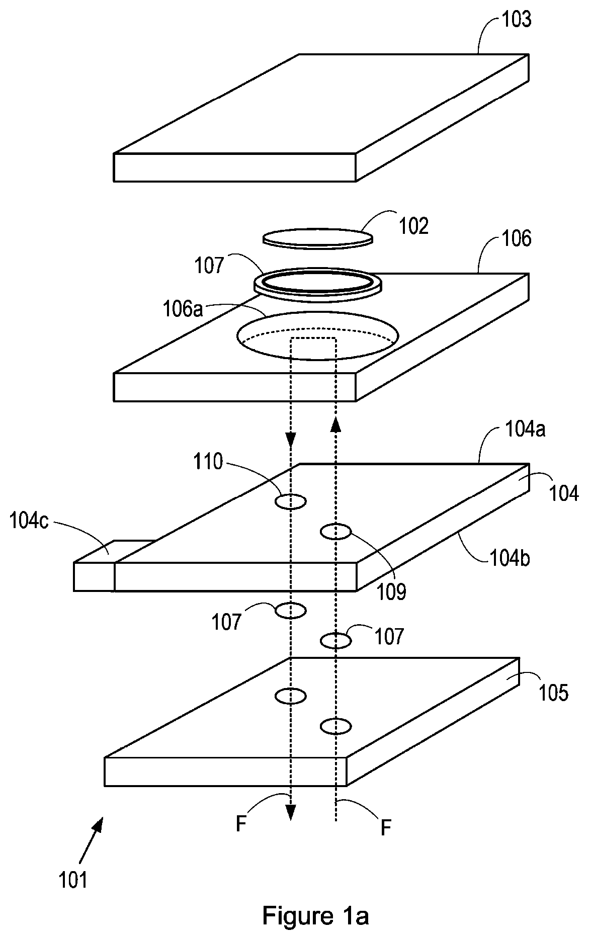
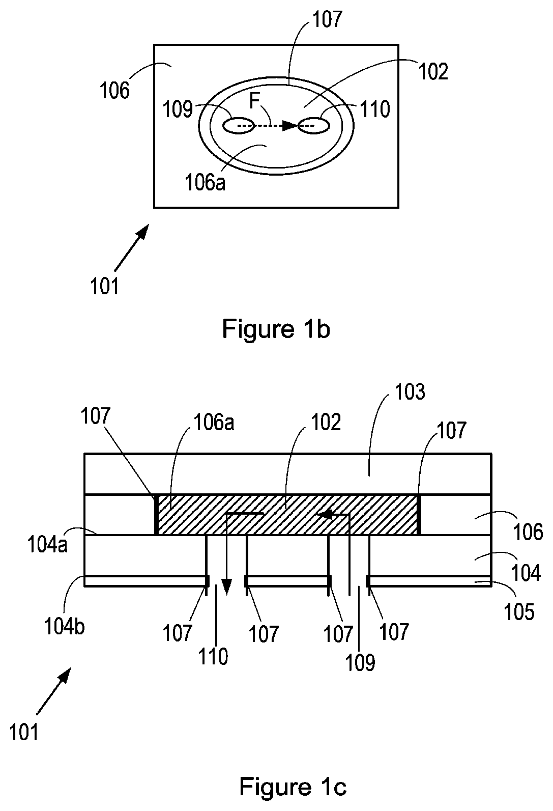
[0097]A redox flow battery containing a single cell was constructed, with the arrangement of components on both sides of the membrane being as shown in FIG. 1A and FIG. 3. The membrane was a Nafion 117 membrane. The dielectric layer 105 was a printed circuit board material, namely FR-4, which was bonded using an epoxy pre-preg (Arlon A47N) to a 0.75 mm thick titanium foil, which acted as the current collector 104. The spacer layer 106 on both sides of the membrane was also FR4, each of which had a circular aperture 106A for accommodating a rubber O-ring comprising material with the trade name Viton (available from Simply Bearings), and, within the O-ring, the electrode, which was a 3D carbon electrode, in particular a 36% compressed SGL carbon felt electrode. Each titanium foil 104 and connected dielectric layer 105 had circular through-holes that act as apertures 109 and 110 shown in FIG. 1B. O-rings were in place around the edge of the apertures in the dielectric layer to prevent ...

example 2

Comparison Between the RFB of Example 1 and Reference RFB

[0099]In this Example, the performance of the redox flow battery of Example 1 was compared with that of a traditional endplate-compressed fuel cell, available from Scribner as part of their trade name Scribner 857 Redox Flow Cell Test System. The Scribner Redox Flow Cell comprises of a graphite plate (obtained from POCO Graphite) into which a flow-field may be machined. The carbon felt electrodes sit on this plate and is usually held in place by a PTFE spacer. The thickness of this spacer also will define the amount of compression of the felt electrode. The current passes through the graphite plate and into a gold coated copper current collector. The whole assembly is held together with two anodized aluminium end plates and 8 bolts. Both used the same all-vanadium couple described above. The Scribner RFB used 50% compressed Alfa Aesar carbon felt electrode and a Nafion 117 membrane. The layers of the Scribner were 25 cm2 in ar...


PUM


Abstract

Herein is disclosed, a rechargeable flow battery, wherein the flow battery comprises: first and second electrodes, separated such that ions are allowed to flow between them, wherein a first reservoir comprising or for holding a first fluid electrolyte is fluidly connected to the first electrode, to allow circulation of the first fluid electrolyte from the first reservoir to the first electrode and from the first electrode to the first reservoir; and a first current collector comprising a layer of electrically conductive material having opposing first and second sides, wherein the first electrode is disposed on the first side of the first current collector, such that electrons can flow from the electrode to the first current collector, and a first layer of dielectric material is disposed on the second side of the first current collector.

Description

BACKGROUND[0001]Large scale energy storage plays an important role in being able spread the energy harnessed from renewable energy storage technologies. Redox flow batteries (RFBs) are a promising candidate for large scale storage of energy harnessed by renewable energy sources such as wind and solar and may also be utilized as standalone power systems and even within vehicular applications. RFBs have a particular advantage of being able to de-couple power from energy: the former is usually a characteristic of the cell(s) architecture (electrode area, operating voltage, etc) whereas the latter is dependent on the volume (and concentration) of electrolyte available. This characteristic enables RFBs to lend themselves to many said applications: due to their inherent design flexibility.[0002]A single RFB cell is typically constructed of two electrodes, which may be carbon-based and / or in the form of felts, cloths, papers, separated by a membrane, which is dependent on the chemistry of ...

Claims


Application Information

Patent Timeline
IPC IPC(8): H01M8/18H01M4/96H01M50/409H01M8/0228H01M8/0202H01M8/0276
CPCH01M8/188H01M4/96H01M8/0278H01M8/0228H01M8/0269H01M50/409H01M8/18Y02E60/50
Inventor BRETT, DANIEL JOHN LESLIEBROWN, LEONMASON, THOMAS JAMESDEDIGAMA, ISHANKAKUCERNAK, ANTHONY ROBERT JOHN
Owner UCL BUSINESS PLC
Why Eureka
Try Eureka