
Management of the cleaning of friction bodies of automotive braking systems

a technology for cleaning friction bodies and automotive braking systems, applied in the direction of braking systems, electric devices, braking components, etc., can solve problems such as certain degree of complexity, and achieve the effect of saving energy

Active Publication Date: 2021-04-01
FCA ITAL
View PDF21 Cites 4 Cited by
  • Summary
  • Abstract
  • Description
  • Claims
  • Application Information

AI Technical Summary

Benefits of technology

The present invention aims to develop a strategy for cleaning the braking systems of automotive vehicles to prevent the negative effects caused by dirt and rust on the braking performance and service life. The strategy should be simpler and have lower impact on the computational resources of the vehicles compared to previous solutions.

Problems solved by technology

The Applicant has found that the previously-described prior art solutions, regardless of whether or not they allow the drawbacks they intend to remedy to be overcome, have a certain degree of complexity at least from the point of view of the logics of management of the operations of the braking mechanism, whose implementation consequently entails a significant exploitation of the computational resources of either the on-board computers or the electronic control units of the motor vehicles.

Method used


Image

  • Management of the cleaning of friction bodies of automotive braking systems
  • Management of the cleaning of friction bodies of automotive braking systems

Examples


Embodiment Construction

[0031]The present invention will now be described in detail with reference to the attached figures to allow a person skilled in the art to reproduce and use it. Various modifications to the described embodiments will be immediately apparent to the persons skilled in the art. The generic principles described can be applied to other embodiments and applications without departing from the scope of protection of the present invention as claimed in the attached claims.

[0032]Therefore, the present invention should not be considered limited to the described and illustrated embodiments, but it must be accorded the widest protective scope in accordance with the described and claimed features.

[0033]Where not defined otherwise, all the technical and scientific terms used herein have the same meaning commonly used by the persons skilled in art pertaining to the present invention. In the event of a contention, this description, including the definitions provided, will be binding. Furthermore, th...


PUM


Abstract

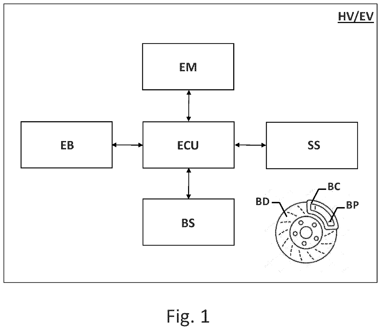
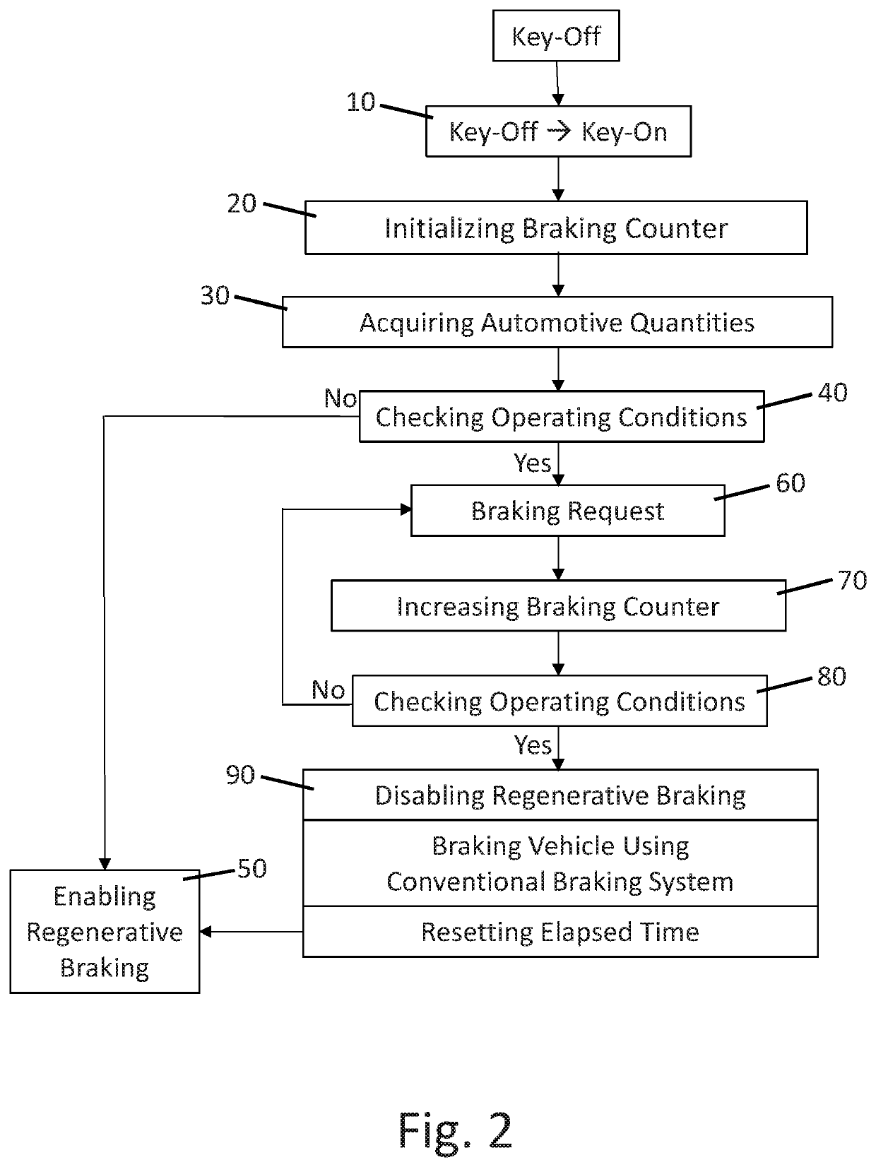
Hybrid or fully electric vehicle comprising: a conventional braking system based on friction bodies to brake the motor vehicle by interaction of the friction bodies in response to the operation of a brake pedal or any other equivalent control member, a reversible electric machine operatively coupled to the wheels of the vehicle and electronically controllable to operate selectively as an electric engine to generate a mechanical power to propel to the vehicle and as an electric generator to convert the kinetic energy of the motor vehicle into electrical energy, and an automotive electronic control system comprising a sensory system to measure automotive quantities, and an electronic control unit to control operation of the conventional braking system and of the electric machine in response to the operation of the brake pedal or any other operationally equivalent control member. The electronic control unit is further configured to control operation of: the electric machine to selectively perform one or more functions including regenerative braking, in which the electric machine is operated as an electric generator to recover the kinetic energy of the motor vehicle during braking and convert it into electrical energy, and the conventional braking system to clean the friction bodies of the conventional braking system based on the number of brakings performed by the conventional braking system and counted starting from the start-up of the motor vehicle.

Description

CROSS-REFERENCE TO RELATED PATENT APPLICATIONS[0001]This application claims priority from European patent application No. 19164119.0 filed on 20 Mar. 2019 and European patent application No. 19177752.3 filed on 31 May 2019, the disclosure of which is incorporated by reference.TECHNICAL FIELD OF THE INVENTION[0002]The present invention relates in general to the field of motor vehicles with (fully) electric propulsion, also known as battery electric vehicles (BEVs), namely motor vehicles with only electric engines powered by electric batteries, and to the field of hybrid propulsion vehicles, namely with an internal combustion engine and an electric engine, of a traditional type, in which the electric batteries are electrically rechargeable with the aid of the internal combustion engines, and of the so-called plug-in (PHEV—Plug-in Hybrid Electric Vehicle) type, in which the electric batteries are electrically rechargeable even without the aid of the internal combustion engines, by usin...

Claims


Application Information

Patent Timeline
Patent Type & Authority Applications(United States)
IPC IPC(8): B60W30/18F16D65/00B60L7/26B60T8/17B60W10/08B60W10/184B60W20/00
CPCB60W30/18127B60W2540/06B60L7/26B60T8/17B60W10/08B60W10/184B60W20/00B60W30/18109B60Y2200/92B60Y2200/91B60T2270/604B60W2540/12B60W2710/08B60W2710/18B60W2510/18B60W2510/244B60W2530/00B60W2530/18B60W2540/18F16D65/0037B60W20/15B60L3/00B60L3/0076B60T8/00B60T2201/124B60W10/188B60W10/26Y02T10/70B60T17/221B60T1/10
Inventor BONACCORSO, GABRIELEENRICO, LUCABADINO, RENATOIELUZZI, MICHELEGALBUSERA, MICHELE
Owner FCA ITAL
Learn More