
Electronically controllable braking system having two fall-back levels

a technology of electronic control and braking system, which is applied in the direction of braking system, braking components, transportation and packaging, etc., can solve the problems of limited deceleration capacity, inability to allow vehicles, and inability of central service brake control module to undertake electrical actuation of service brakes, etc., to achieve no negative effect on the performance and robustness of the service brake system

Pending Publication Date: 2022-05-12
ZF CV SYST EURO BV
View PDF0 Cites 4 Cited by
  • Summary
  • Abstract
  • Description
  • Claims
  • Application Information

AI Technical Summary

Benefits of technology

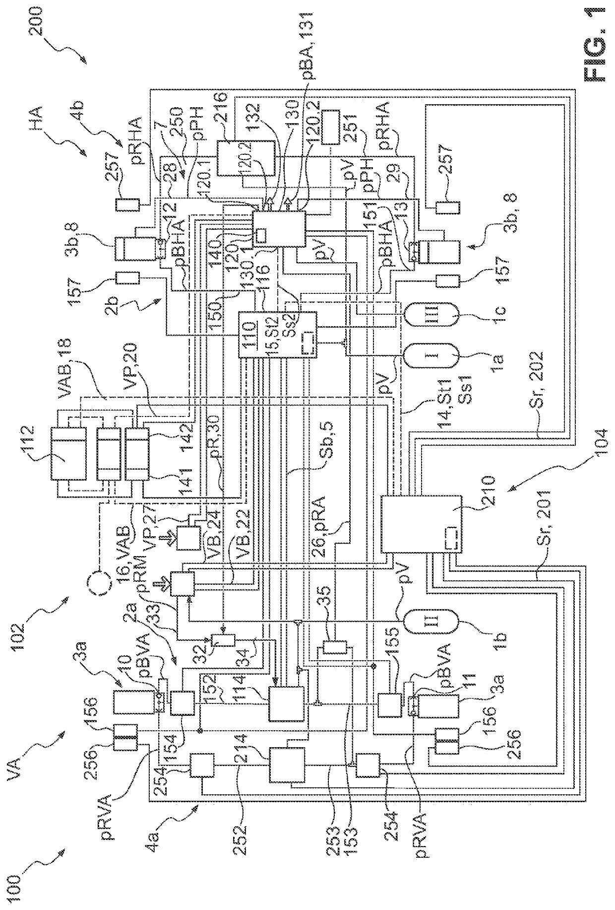
The disclosed invention provides a braking system for vehicles that can still operate in case of single faults. The system is designed to have a low cost and not affect the performance and reliability of the service brakes. This ensures that the vehicle can still travel safely, either to its destination or a repair shop.

Problems solved by technology

This can lead to a limited deceleration capacity and optionally to additional instabilities while the vehicle is moving.
This has the disadvantage that, in electronically controlled braking systems which control the service brakes at the rear axle and the front axle, and optionally further vehicle axles, via the pressure modulator via only a central service brake control module, such compensation cannot take place, since, in the event of a failure of the energy source or of individual electrical components of the service brake circuit in question, the central service brake control module can no longer undertake the electrical actuation of the service brakes, or of the pressure modulators upstream thereof, at individual vehicle axles.
A problem here is that all these systems are aimed primarily at a residual availability in the case of single faults, in order to bring the vehicle into a safe state.
They are generally not suitable for allowing the vehicle to travel onwards to its destination.
If implementation of the braking specification by the service brake control module is not possible, it is conceivable that the service brake control module transmits a fault signal.
In this manner it is possible that the trailer is also concomitantly redundantly braked if there is a fault in the braking system which prevents normal outputting of the trailer brake pressure.

Method used


Image

  • Electronically controllable braking system having two fall-back levels
  • Electronically controllable braking system having two fall-back levels
  • Electronically controllable braking system having two fall-back levels

Examples


second embodiment

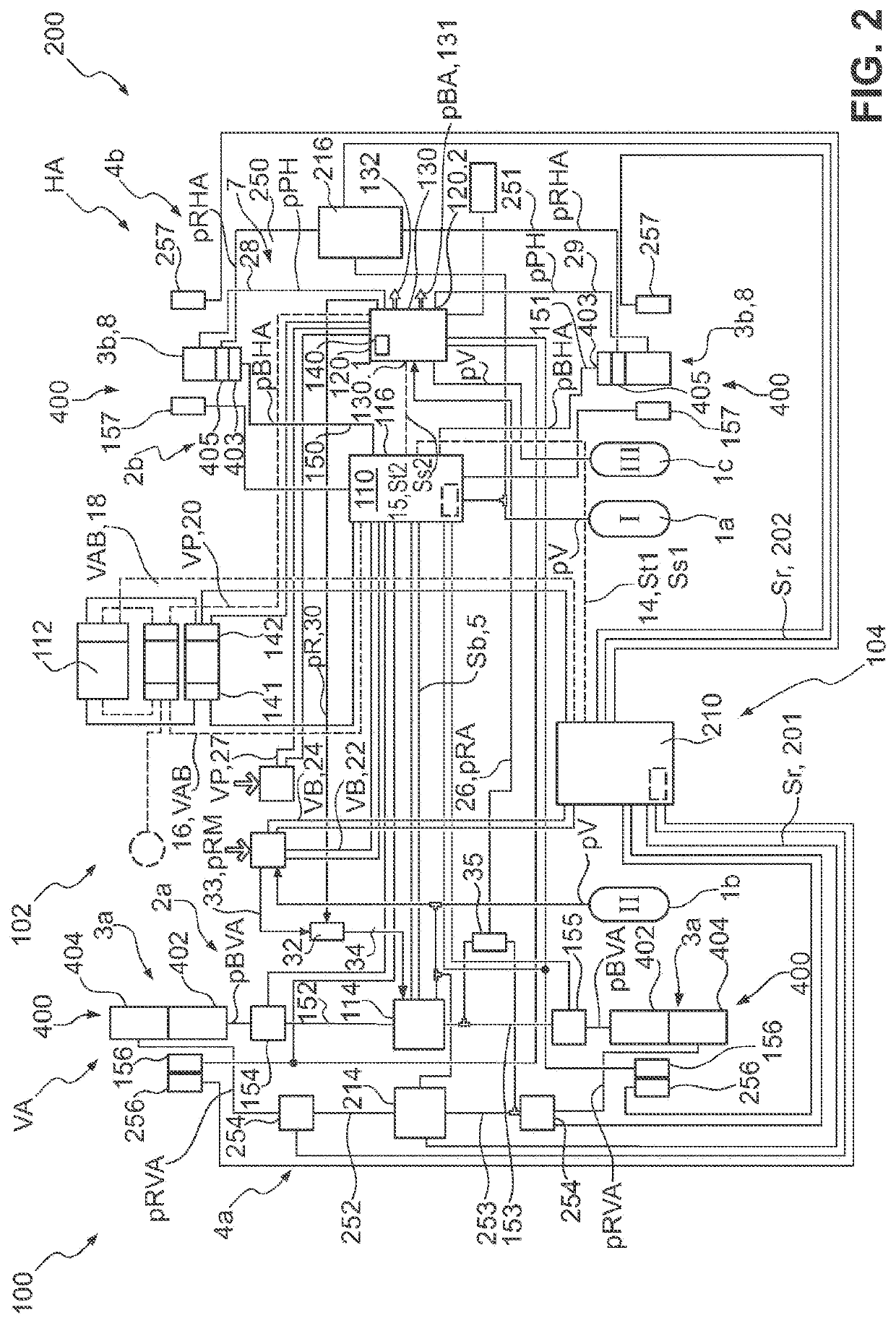
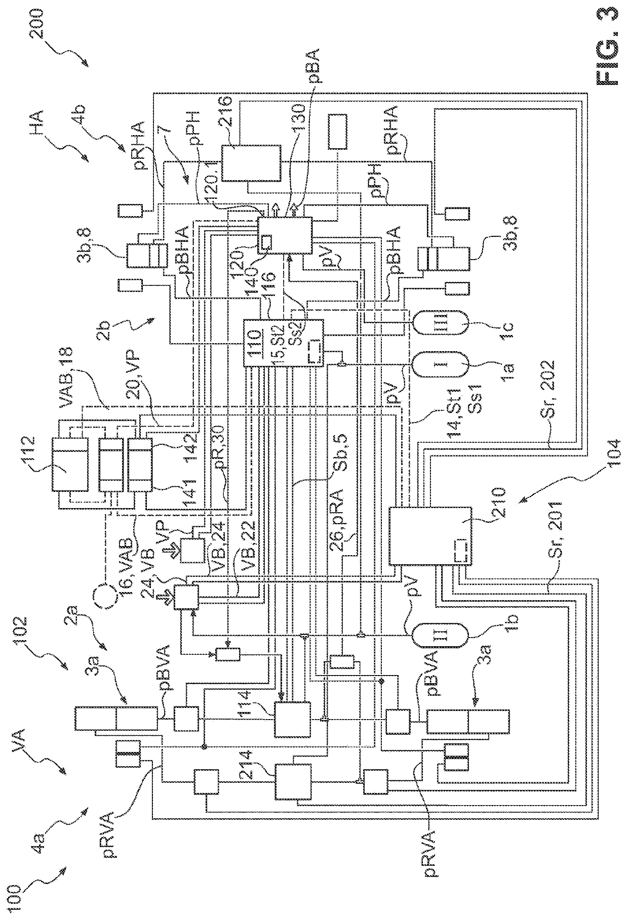
[0070]In a third exemplary embodiment (as depicted in FIG. 3), a braking system 100 which is based on the second exemplary embodiment (as depicted in FIG. 2) is shown. Identical and similar elements are again denoted by the same reference designations, such that reference is made to the above description relating to the first and second embodiment in its entirety. In the following, the differences between the first and second exemplary embodiment will be highlighted in particular.

[0071]The fundamental difference in the third exemplary embodiment relative to the second exemplary embodiment lies in the fact that the first compressed air reservoir 1a is connected to the rear axle service brake circuit 2b and to the front axle redundancy brake circuit 4a. In the same manner, the second compressed air reservoir 1b is connected to the front axle service brake circuit 2a and to the rear axle redundancy brake circuit 4b. This means that the first compressed air reservoir 1a provides supply ...

sixth embodiment

[0075]The sixth exemplary embodiment (as depicted in FIG. 7) differs from the first exemplary embodiment (as depicted in FIG. 1) in that the brake signal transmitter BST is not in pneumatically redundant form. The brake signal transmitter BST is electrically connected solely via the first brake signal transmitter line 22 and the second brake signal transmitter line 24 to the service brake control module 110 and the redundancy brake control module 210. However, the brake signal transmitter BST is not connected either to the second compressed air reservoir 1b or to the second redundancy line 33. In this respect, the first redundancy pressure line 30 is connected directly to the service front axle modulator 114 in order to output the redundancy pressure pR at the service front axle modulator. Manual, pneumatically redundant control is not provided in this braking system 100 according to the

[0076]The seventh exemplary embodiment (as depicted in FIG. 8) is again based on the second exemp...


PUM


Abstract

An electronically controllable braking system for a vehicle is provided. The electronically controllable braking system includes a service brake sub-system and a redundancy brake sub-system. The service brake sub-system includes a front axle service brake circuit with front axle service brakes and a rear axle service brake circuit with rear axle service brakes. The redundancy brake sub-system includes a front axle redundancy brake circuit and a rear axle redundancy brake circuit. A service brake control module is configured to generate a service brake control signal in dependence upon a braking specification for generating a front axle service brake pressure. A redundancy brake control module is configured to generate a redundancy brake control signal in dependence upon a braking specification for generating a front axle redundancy brake pressure.

Description

CROSS-REFERENCE TO PRIOR APPLICATIONS[0001]This application is a U.S. National Phase application under 35 U.S.C. § 371 of International Application No. PCT / EP2020 / 055666, filed on Mar. 4, 2020, and claims benefit to German Patent Application No. DE 10 2019 106 591.7, filed on Mar. 15, 2019. The International Application was published in German on Sep. 24, 2020 as WO 2020 / 187569 under PCT Article 21(2).FIELD[0002]The disclosure relates to an electronically controllable braking system, in particular an electronically controllable pneumatic braking system, for a vehicle, in particular a commercial vehicle, at least comprising a service brake sub-system having a front axle service brake circuit with front axle service brakes, a rear axle service brake circuit with rear axle service brakes, and a service brake control module, wherein there can be supplied to the front axle service brakes a front axle service brake pressure and to the rear axle service brakes a rear axle service brake pre...

Claims


Application Information

Patent Timeline
IPC IPC(8): B60T8/94B60T8/88B60T8/17B60T13/26B60T13/68B60T8/176
CPCB60T8/94B60T8/885B60T8/1708B60T2270/413B60T13/683B60T8/176B60T13/268B60T8/345B60T8/88B60T13/662B60T17/18B60T17/22B60T17/083
Inventor VAN THIEL, JULIAN
Owner ZF CV SYST EURO BV
Learn More