
Passive multi-core repeater for wireless power charging

a repeater and wireless power technology, applied in the direction of transformers, electrical devices, inductances, etc., can solve the problems of increasing the cost of the repeater, and affecting the service life of the customer

Pending Publication Date: 2021-02-11
POWERMAT TECHNOLOGIES
View PDF0 Cites 1 Cited by
  • Summary
  • Abstract
  • Description
  • Claims
  • Application Information

AI Technical Summary

Benefits of technology

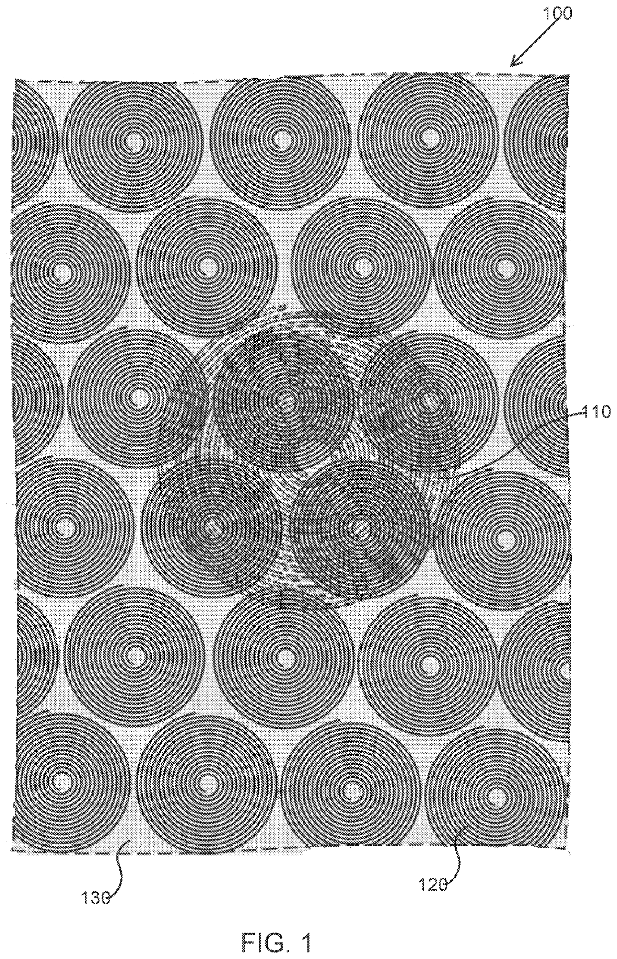
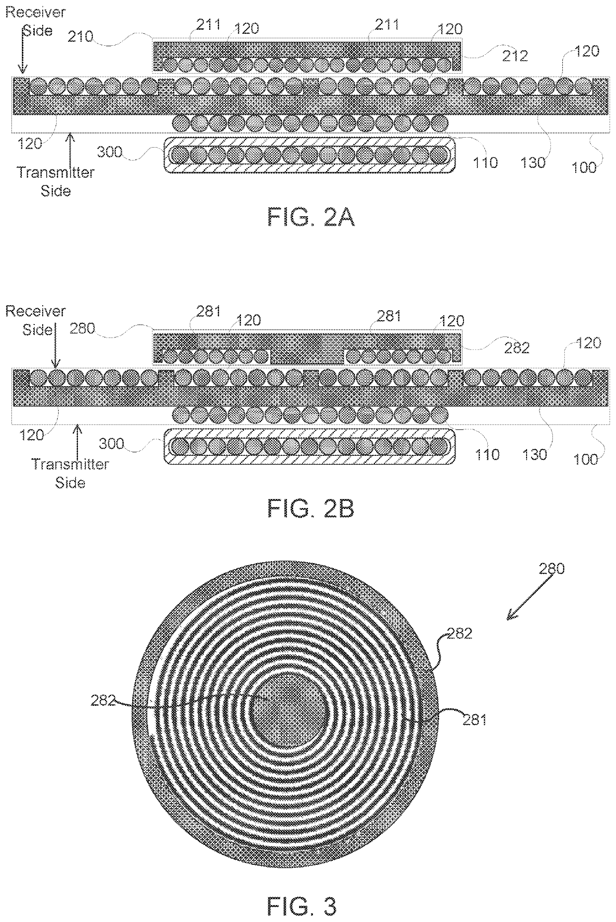
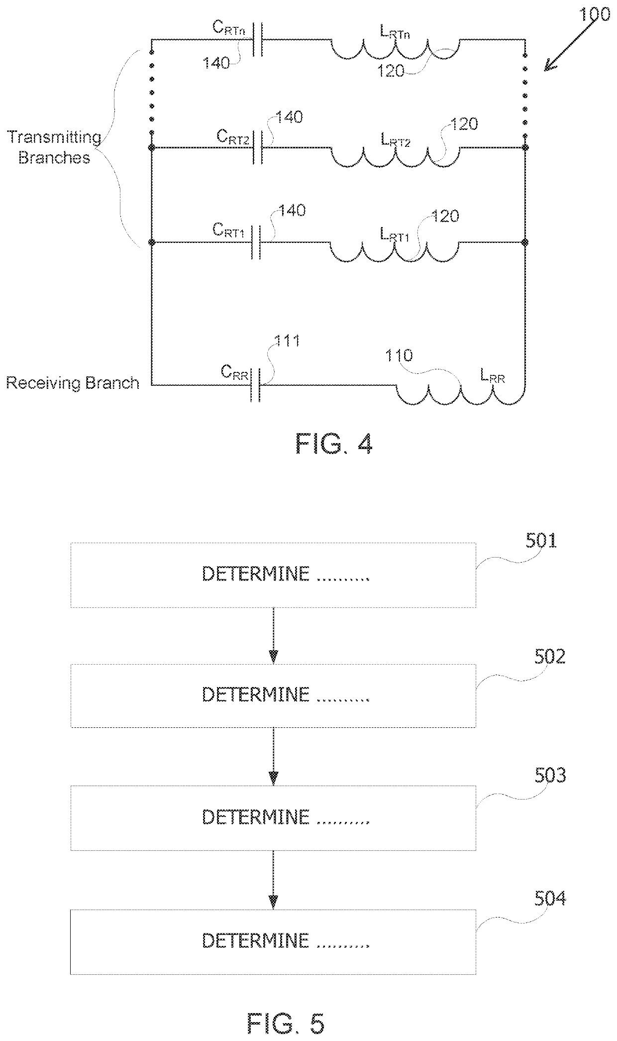
The present disclosed subject matter is about a multi-coil repeater for wireless power transfer from a transmitter to a receiver coil. The repeater has an adjustable operation frequency and includes an array of passive repeater transmitting coils, a ferrite layer with a receiver facing side, and a repeater receiving coil with a transmitter facing side. Each RTC has a resonance capacitor to form a branch with a resonance frequency, and the resonance frequency of at least one branch situated below the receiver changes when a receiver is placed above it. The transmitter adjusts its operational frequency to the RRC to be close to the different resonance frequency of the branches. The method of adjusting an operational frequency involves scanning a range of frequencies and registering power output for each frequency. The repeater ensures power needs of the receiver and adjusts its power output accordingly. The technical effect of the invention is to optimize the efficiency of wireless power transfer between the transmitter and receiver by selecting the proper branch of the repeater coil system.

Problems solved by technology

Typically, the systems are installed on top of surfaces, such as tables, bars, or the like that are accessible to users, thus require decorative appearance and hazards free installation.
This complicates the installation and raises its cost, on top of damaging the customer's furniture.

Method used


Image

  • Passive multi-core repeater for wireless power charging
  • Passive multi-core repeater for wireless power charging
  • Passive multi-core repeater for wireless power charging

Examples


Embodiment Construction

[0029]Before explaining at least one embodiment of the disclosed subject matter in detail, it is to be understood that the disclosed subject matter is not limited in its application to the details of construction and the arrangement of the components set forth in the following description or illustrated in the drawings. The disclosed subject matter is capable of other embodiments or of being practiced or carried out in various ways. Also, it is to be understood that the phraseology and terminology employed herein is for the purpose of description and should not be regarded as limiting. The drawings are generally not to scale. For clarity, non-essential elements were omitted from some of the drawings.

[0030]The terms “comprises”, “comprising”, “includes”, “including”, and “having” together with their conjugates mean “including but not limited to”. The term “consisting of” has the same meaning as “including and limited to”.

[0031]The term “consisting essentially of” means that the compo...


PUM


Abstract

A multi-coil repeater is provided for wireless power transfer from a transmitter, having an adjustable operation frequency, to a receiver coil having a ferrite layer behind it, the multi-coil repeater comprising: an array of passive repeater transmitting coils (RTC) in a single layer; a ferrite layer having a receiver facing side and a transmitter facing side, wherein the array is positioned on the receiver facing side; and a repeater receiving coil (RRC) positioned on the transmitter facing side; wherein each RTC of the array has a resonance capacitor to form a branch having a resonance frequency, wherein all branches are parallelly wired together, wherein a receiver placed above the receiver facing side causes the resonance frequency of at least one branch situated directly below the receiver to drop to a different resonance frequency; and wherein the transmitter adjusts its operational frequency to the RRC to be close to the different resonance frequency of the at least one branch.

Description

CROSS-REFERENCE TO RELATED APPLICATION[0001]This application claims priority from co-pending; U.S. Provisional Patent Application No. 62 / 626,094, by Itay Sherman, titled “Fully passive multi coil array for wireless power”, filed Feb. 4 2017; which is incorporated by reference for all purposes.TECHNICAL FIELD[0002]The present disclosed subject matter relates to wireless power charging systems. More particularly, the present disclosed subject matter relates to passive repeater and methods for wireless power charging.BACKGROUND[0003]Growing demand for wireless power charging systems led to dramatic deployments increase, in a wide variety of venues, that consequently raises the need for increasing the effective charging area and distance between the transmitter and the receiver in the system.[0004]Wireless power charging systems are usually deployed in public facilities such as restaurants, coffee shops, airports, bus stations; train stations, banks, schools, libraries, hotels, official...

Claims


Application Information

Patent Timeline
IPC IPC(8): H02J50/40H02J50/12H02J50/80
CPCH02J50/402H02J50/80H02J50/12H02J50/50H01F38/14
Inventor SHERMAN, ITAY
Owner POWERMAT TECHNOLOGIES
Learn More