
Method and device for measuring resistance of resistive sensor

a technology of resistive sensor and measuring device, which is applied in the direction of altering the measuring range circuit, static storage, voltage divider, etc., can solve the problems of inability to measure accurately, the resolution of measurement is getting substantially worse, and the use of means can be inappropriate, so as to achieve the effect of high sensitivity of the measuring device, and no risk of damage to the sensor

Active Publication Date: 2021-01-28
UNIV PALACKEHO V OLOMOUCI
View PDF0 Cites 0 Cited by
  • Summary
  • Abstract
  • Description
  • Claims
  • Application Information

AI Technical Summary

Benefits of technology

The invention is a measuring device that has a high range of sensitivity and uses low amplitude alternating voltage for safety. It has a high input resistance, which prevents parasitic resistance from affecting the circuit. The device also suppresses parasitic capacitances and increases the used frequency of applied voltage for a faster response rate. The device contains at least two branches connected in parallel, which results in the increase of sensitivity. An analog or digital filter is used to remove disturbances caused by electromagnetic interference. The device has a permanently connected branch resistor that reduces the overall resistance of the actively controlled resistor network.

Problems solved by technology

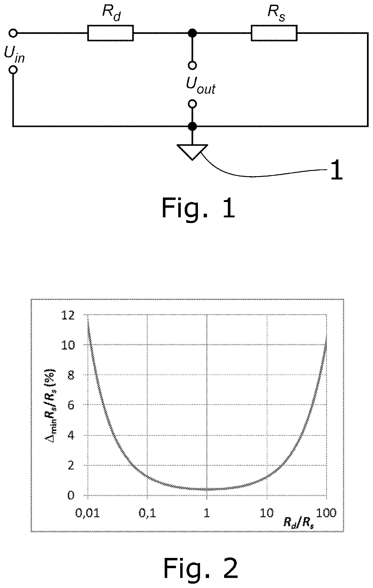
It is obvious that the resolution of measurement is getting substantially worse if Rd and Rs differ by more than one order of magnitude.
When the resistance of the sensor varies in a wide range, a single resistor may not be sufficient, and the measuring circuit must contain more resistors connected into the divider manually or by electronic selector according to the actual values of resistance of the sensor.
Especially in the case of high resistance of the sensor, and thus of the resistor of the divider as well (MΩ and higher), the measuring is complicated by electromagnetic interference (EMI) which is effectively captured by connecting conductors.
However, depending on the required parameters of the device and circumstances of its usage, such means can be inappropriate.
Shielding increases requirements for space and can complicate the installation of the sensor into the measured environment.
A disadvantage is the risk of facilitating electrochemical changes in the sensor (humidity sensors) and the necessity to provide corresponding power supply; an obstruction in this approach is that the maximum applied voltage of some types of sensors is limited.
Drawbacks of the state of the art include the necessity to shield electromagnetic interference caused by the presence of external electric fields for example of electrical wiring in walls, radiation of electronic devices in the environment.
Negative result of usage of the high voltage is a possible damage to the sensor and decrease in safety while working with the measuring device.
Present solutions do not offer a measuring device with high sensitivity as well as a wide range of resistance change of the sensor.

Method used


Image

  • Method and device for measuring resistance of resistive sensor
  • Method and device for measuring resistance of resistive sensor
  • Method and device for measuring resistance of resistive sensor

Examples


Embodiment Construction

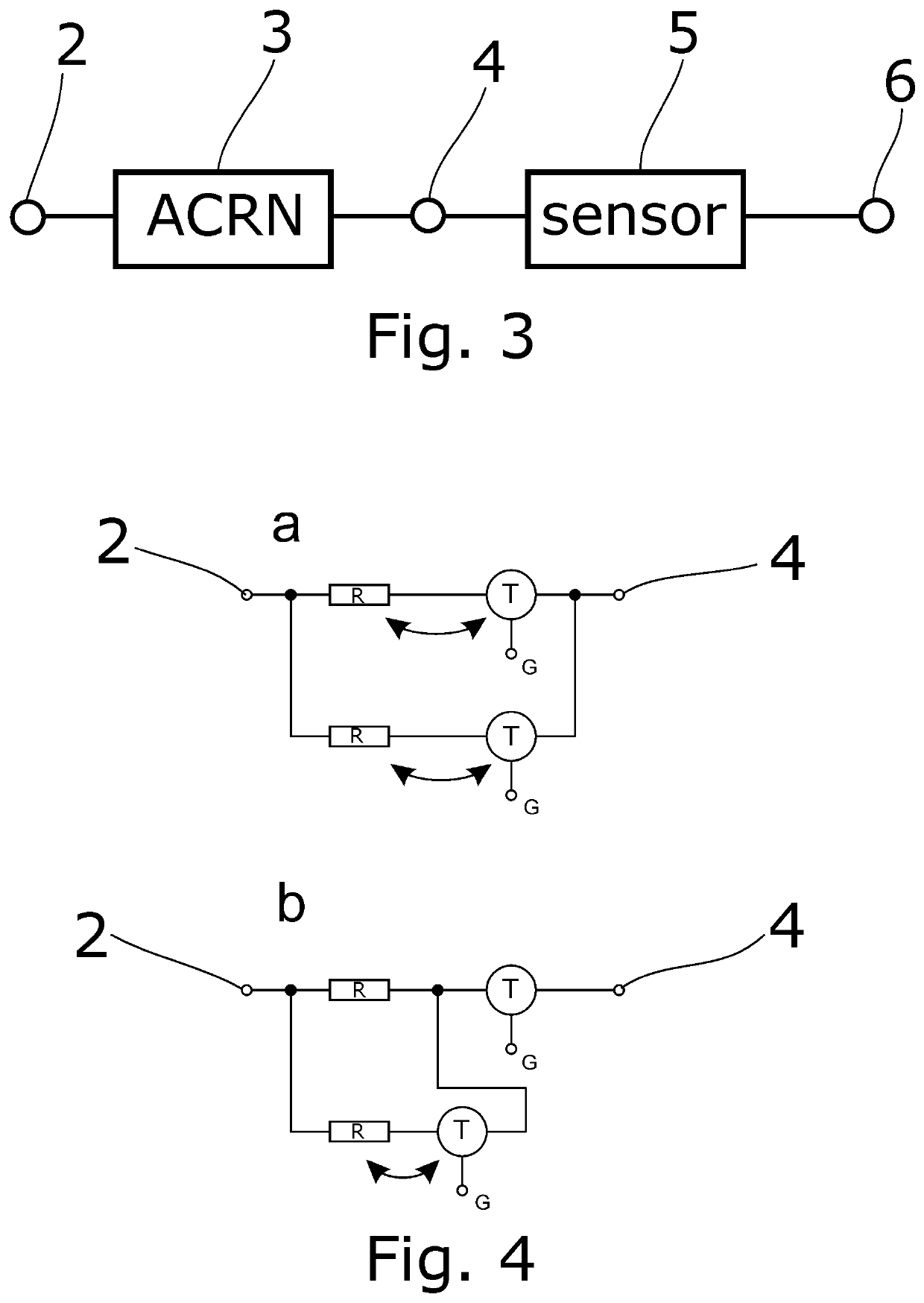
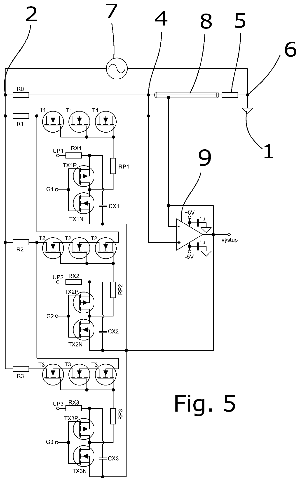
[0031]The basis of the invention is a voltage divider formed by the connection of the actively controlled resistor network 3 (referred to as ACRN) with two terminals between the nodes A 2 and B 4, and a sensor 5 between the nodes marked as B 4 and C 6, see FIG. 3. ACRN 3 includes an arrangement of two or more branches 10 that contain an element with defined resistance (resistor) and a switching element, which is a unipolar transistor. Preferably, the switching element is formed by series connection of multiple switching transistors T1. Two ways of mutual arrangement of two branches 10 in ACRN 3 are apparent from FIG. 4. If a variable arrangement of the resistor and the transistor is possible, it is marked in the diagram by a two-way arrow. Other branches 10 can be added to ACRN 3 in an analogous manner. Connection of a given branch resistor into the divider is carried out by switching on the switching transistors, which are between the branch resistor and the node A 2, or B 4. The i...


PUM


Abstract

The invention refers to a method of measuring resistance of the resistive sensor (5), where the value of resistance of the resistive sensor (5) is determined from its series connection with actively controlled resistor network (3) with selectable value of resistance and with a periodic waveform voltage source (7), and further a device for measuring resistance of the resistive sensor (5) including a periodic waveform voltage source (7), actively controlled resistor network (3), and a resistive sensor (5), wherein the terminals of the periodic waveform voltage source (7) are connected to node A (2) and C (6), terminals of actively controlled resistor network (3) are connected to node A (2) and B (4), and terminals of the resistive sensor are connected to node B (4) and C (6), thus forming a connection in a resistive voltage divider with an automatic selection of one resistor of the divider, and usage of this method for measuring time-varying resistance of the sensor.

Description

FIELD OF THE INVENTION[0001]The invention relates to measuring resistance of a sensor, which is controlled by a resistive divider with an automatic selection of a resistor of the divider mostly for higher accuracy, rate and safety of the process.STATE OF THE ART[0002]Sensing of many physical and physico-chemical quantities (e.g. temperature, luminous flux, deformation, concentration) is done by resistive sensors, the value of resistance of the sensor being in certain causal relationship with the value of measured quantity. Different measuring methods for determining the resistance of the sensor are used. Basically, it is a connection of the sensor to a simple voltage divider with a resistor of a known resistance value, connection to a resistance bridge, measuring of voltage drop during the passage of a known forced current, and measuring or integration of the passing current with a known applied voltage. The selection of particular measuring method is done with respect to the requir...

Claims


Application Information

Patent Timeline
Patent Type & Authority Applications(United States)
IPC IPC(8): G01R27/14G01R15/08G01R15/04
CPCG01R27/14G01R15/04G01R15/08G01R27/02G11C29/56G01R31/00G01R31/2889
Inventor FRYCÁK, PETR
Owner UNIV PALACKEHO V OLOMOUCI
Learn More