
Dual polarised omnidirectional antenna apparatus

Active Publication Date: 2020-12-31
THE SEC OF STATE FOR DEFENCE IN HER BRITANNIC MAJESTYS GOVERNMENT OF THE UK OF GREAT BRITAIN & NORTHERN IRELAND
View PDF18 Cites 1 Cited by
  • Summary
  • Abstract
  • Description
  • Claims
  • Application Information

AI Technical Summary

Benefits of technology

The invention is a dual polarised omnidirectional antenna apparatus that can transmit and receive signals using electromagnetic radiation. The antenna apparatus consists of at least two dual polarised directional antennas that are mounted on a platform in a distributed array around and pointing away from the platform. The antennas operate in phase with each other to deliver a combined omnidirectional performance, providing increased gain and available bandwidth compared to single monopole or dipole antennas. The antenna apparatus can be used for search and rescue, military applications, and other applications where omnidirectional performance is required. The use of directional antennas reduces the amount of power needed and the size and weight of auxiliary components, making it easier to wear or mount on a vehicle. The dual polarised antennas can transmit or receive using two orthogonal polarisations simultaneously, providing effective de-correlation and de-interference capabilities. The method of omnidirectional communication involves mounting the dual polarised directional antennas on a platform, providing in-phase power, and then receiving or transmitting signals using the antenna apparatus. This results in a high gain omnidirectional antenna with improved bandwidth and interference mitigation.

Problems solved by technology

This has conventionally been achieved using monopole or dipole ‘whip’ type antennas, although such antennas are prone to snagging and not well suited to space constrained applications.
Conventional omnidirectional antennas are limited in respect of their ability to cater for such improvements.

Method used


Image

  • Dual polarised omnidirectional antenna apparatus
  • Dual polarised omnidirectional antenna apparatus
  • Dual polarised omnidirectional antenna apparatus

Examples


Embodiment Construction

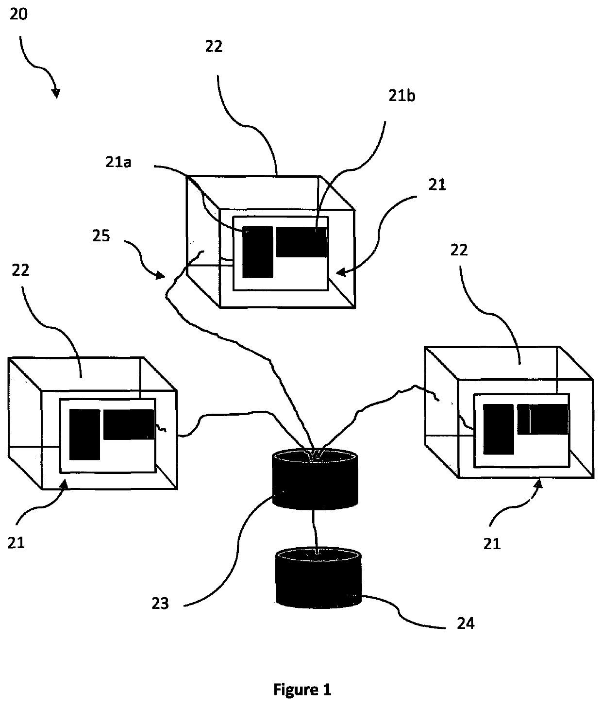
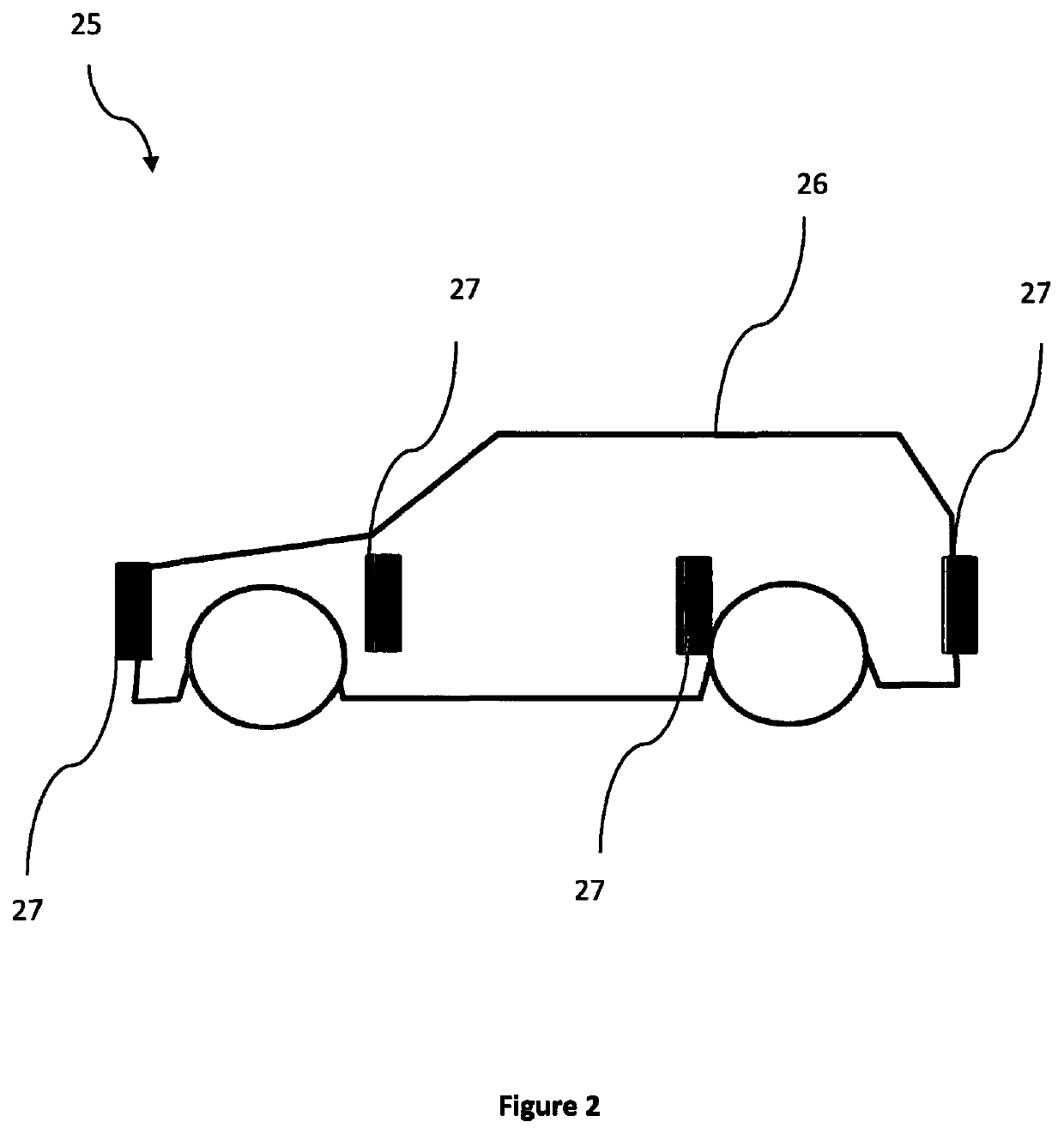
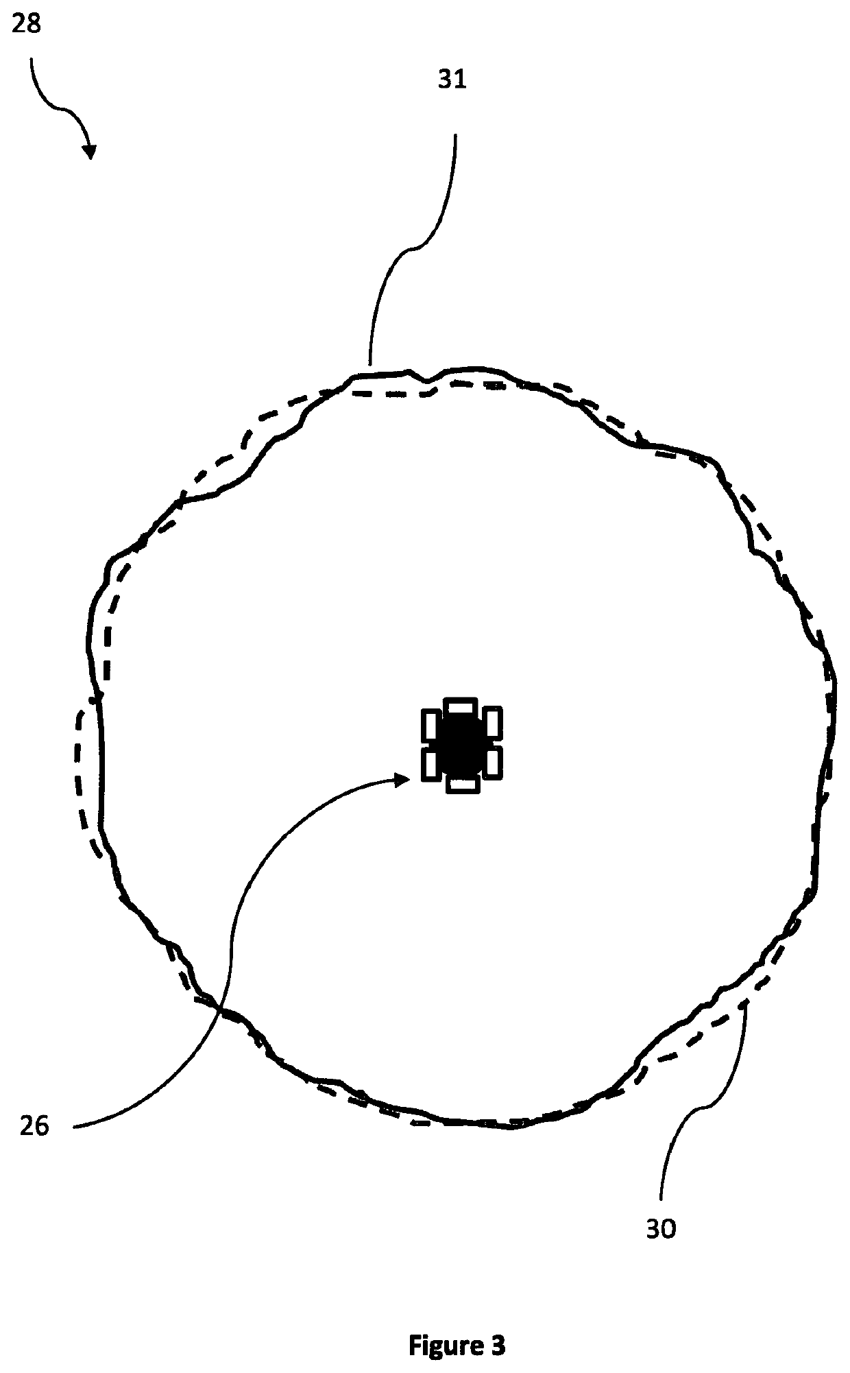
[0023]FIG. 1 shows an illustration of a plurality of dual polarised directional antennas 21 configured as an embodiment of an omnidirectional antenna apparatus 20. Dual polarised directional antennas 21 are shown inside respective protective radomes 22 to protect against damage or abrasion. The radomes 22 are formed from plastic and are transparent to the radio frequencies of operation of antennas 21. Each antenna 21 is electrically connected (via wires 25) to a transmitter 23, itself being electrically connected to power supply 24. The power supply 24 is a portable battery unit (for instance lithium ion battery or other electrolyte based battery, such as would be found in a vehicle). The electrical connections 25 to each antenna 21 are split inside antenna 21 via respective power dividers (not shown) so as to power both antenna elements 21a and 21b in each antenna 21. The power divider inside each antenna 21 equally divides power to the respective first 21a and second 21b antenna e...


PUM


Abstract

A dual polarised omnidirectional antenna apparatus (20) capable of operating in transmit and receive, comprising at least two dual polarised directional antennas (21) configured to be mountable in a substantially equi-spaced distributed array around and pointing away from a platform, wherein the antenna apparatus (20) is configured such that, when operated in transmit, the dual polarised directional antennas operate in phase with each other to deliver a combined omnidirectional, dual polarised, performance. This increases operational bandwidth and mitigates interference effects in communications applications.

Description

TECHNICAL FIELD OF THE INVENTION[0001]This invention relates to the field of omnidirectional antennas, in particular to omnidirectional antennas providing dual polarisation.BACKGROUND TO THE INVENTION[0002]Antennas are used for transmitting and receiving signals in various wireless applications. For instance antennas are widely used for communications, search and rescue, security and other military applications. Antennas are not only standalone devices, but can also be integrated into many different types of products ranging from antennas integrated as body wearable devices, antennas integrated into handsets / mobile personal digital assistants (PDAs) and vehicle / platform mounted antennas with associated systems. These different applications will have their own performance requirements that include, but are not limited to, weight, compactness, ergonomics, ruggedness and power consumption.[0003]Omnidirectional antennas are used in many communications applications, in particular in appl...

Claims


Application Information

Patent Timeline
IPC IPC(8): H01Q21/24H01Q21/20H01Q1/24H01Q25/00
CPCH01Q1/246H01Q25/001H01Q21/205H01Q21/24H01Q1/32H01Q3/34
Inventor BOYES, STEPHEN JOHN
Owner THE SEC OF STATE FOR DEFENCE IN HER BRITANNIC MAJESTYS GOVERNMENT OF THE UK OF GREAT BRITAIN & NORTHERN IRELAND
Learn More