
Energy compensated equipower density oblique laser shock method

a laser shock and density technology, applied in the field of energy compensation equipower density oblique laser shock method, can solve the problem of unfavorable laser shock peening effect, and achieve the effect of improving the evenness of residual stress distribution

Active Publication Date: 2020-12-31
GUANGDONG UNIV OF TECH
View PDF0 Cites 2 Cited by
  • Summary
  • Abstract
  • Description
  • Claims
  • Application Information

AI Technical Summary

Benefits of technology

The present invention provides an energy compensated equipower density oblique laser shock method that compensates for changes in the incident angle and radius of curvature of a part being processed. This ensures that the laser power density remains constant in the same area or on the same trajectory, improves the evenness of residual stress distribution, enhances the shock effect, and reduces roughness of the laser shock processed surface. Compared to existing methods, the energy compensated method achieves isointensity peening and improves overall quality of laser shock processing.

Problems solved by technology

As the incident angle and an arc angle are changed, the shape and area of the projection plane of the laser beam on the surface are also changed, causing uneven laser shock peening effect.

Method used


Image

  • Energy compensated equipower density oblique laser shock method
  • Energy compensated equipower density oblique laser shock method
  • Energy compensated equipower density oblique laser shock method

Examples


embodiment 1

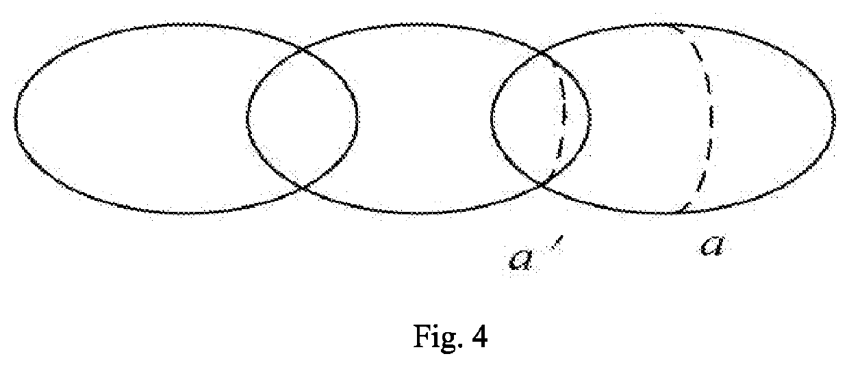
[0033]FIG. 1 to FIG. 4 show the first embodiment of an energy compensated equipower density oblique laser shock method, including the following steps:

[0034]S1. acquiring a radius of curvature R of an arc peening region of a part to be processed and morphological characteristics thereof, judging a range of a laser incident angle α, and acquiring a minimum incident angle αmin. In the present embodiment, the range of the laser incident angle α is αmin≤α<90°, the part to be processed in the present embodiment is an impeller including a bladed disk and a blade, and the arc region is arranged at the joint of the bladed disk and the impeller;

[0035]S2: determining, according to a mechanical property of the part to be processed and a processing strength requirement thereof, laser parameters including laser pulse intensity, a spot diameter D, and required laser energy Eo under a vertical incidence condition;

[0036]S3. determining required laser energy E at the minimum incident angle αmin accor...


PUM

PropertyMeasurementUnit
Lengthaaaaaaaaaa
Angleaaaaaaaaaa
Densityaaaaaaaaaa

Abstract

The present invention relates to the technical field of material surface peening, and more particularly to an energy compensated equipower density oblique laser shock method. The method includes: acquiring a radius of curvature of a peening region of a part to be processed, and judging a range of a laser incident angle; determining laser parameters, such as laser pulse width, a spot diameter, and required laser energy under a vertical incidence condition; calculating the required laser energy at the minimum incident angle, and judging whether the energy falls within the technical indexes of a laser; and performing laser shock peening on the part by pulse laser beams with different energies. According to the present invention, the laser power or energy is compensated according to changes in the incident angle and the radius of curvature of the part to be processed.

Description

CROSS-REFERENCE TO RELATED APPLICATIONS[0001]This application is a continuation of International Application No. PCT / CN2018 / 102599, filed on Aug. 28, 2018, which claims the benefit of priority from Chinese Patent Application No. 201810483359.7 filed on May 18, 2018. The content of the aforementioned applications, including any intervening amendments thereto, is incorporated herein by reference.TECHNICAL FIELD[0002]The present invention relates to the technical field of material surface peening, and more particularly, to an energy compensated equipower density oblique laser shock method.BACKGROUND OF THE PRESENT INVENTION[0003]Laser shock, which is a technology of peening metal by shock waves inducted by strong laser, can substantially enhance the durability of metal materials. Laser has good reachability and accurate positioning; therefore, laser shock peening technology can be performed on some parts that cannot be processed by traditional surface peening. The laser shock peening t...

Claims


Application Information

Patent Timeline
IPC IPC(8): C21D10/00B23K26/356
CPCB23K26/356C21D10/005B23K26/032C21D7/06
Inventor ZHANG, YONGKANGZHOU, ZEMINGLIN, CHAOHUIZHANG, ZHENGLU, GUOXIN
Owner GUANGDONG UNIV OF TECH
Learn More