Fuel strainer for an in-tank fuel pump

a fuel pump and fuel strainer technology, which is applied in the direction of machines/engines, filtration separation, separation processes, etc., can solve the problems of complex and costly implementation of fuel strainers, and achieve the effects of maximizing the effectiveness of the magnet, minimizing the restriction of flow, and simple and economical production

Inactive Publication Date: 2020-12-10
DELPHI TECH IP LTD
View PDF1 Cites 0 Cited by
  • Summary
  • Abstract
  • Description
  • Claims
  • Application Information

AI Technical Summary

Benefits of technology

[0007]The fuel strainers as described herein allow for capture of ferrous foreign matter in a design which is simple and economical to produce and which maximizes effectiveness of the magnet while minimizing restriction of flow to the fuel pump inlet.

Problems solved by technology

However, ferrous foreign matter, for example resulting from rusting of the fuel tank or other fuel system components, may be present in the fuel and may be sufficiently small so as to pass through the fuel strainer and pass to the in-tank fuel pump.
Furthermore, ferrous foreign matter that may be sufficiently large to be captured by the fuel strainer may tend to be captured in one localized area of the fuel strainer near the inlet of the fuel pump which can restrict fuel flow to the fuel pump.
Chinese Utility Model CN 201826998 discloses a fuel strainer which includes a magnet to capture ferrous foreign matter, however, one embodiment incorporates the magnet as a frame of the fuel strainer which is complex and costly to implement.

Method used


Image

  • Fuel strainer for an in-tank fuel pump
  • Fuel strainer for an in-tank fuel pump
  • Fuel strainer for an in-tank fuel pump

Examples


Embodiment Construction

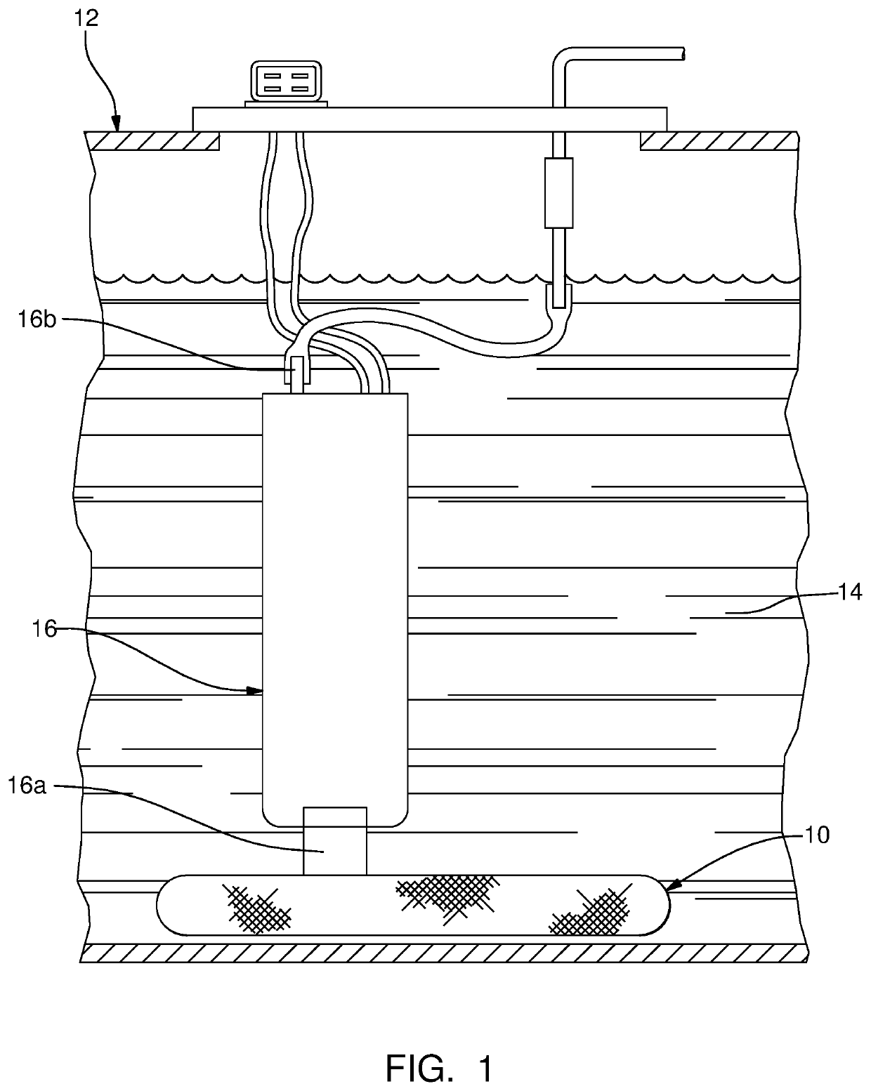
[0015]Referring initially to FIG. 1, a fuel strainer 10 is shown in a fuel tank 12 which holds a volume of fuel 14, by way of non-limiting example only, gasoline, alcohol, diesel fuel, ethanol, or blends containing one or more of the foregoing. Fuel tank 12 may be formed of metal or plastic in configurations that are known to those of skill in the art. Also within fuel tank 12 is an in-tank fuel pump 16 which includes a fuel pump inlet 16a through which in-tank fuel pump 16 draws fuel from volume of fuel 14 and also includes a fuel pump outlet 16b through which in-tank fuel pump 16 discharges fuel to be sent to a fuel consuming device, for example, an internal combustion engine (not shown). In-tank fuel pump 16 may be constructed, by way of non-limiting example only, in accordance with the disclosure of U.S. Patent Application Publication No. 2014 / 0314591 A1 to Herrera et al., the entire disclosure of which is incorporated herein by reference in its entirety. Fuel strainer 10 is att...


PUM

PropertyMeasurementUnit
thicknessaaaaaaaaaa
sizeaaaaaaaaaa
volumeaaaaaaaaaa

Abstract

A fuel strainer includes a first panel of filtration media having a filtration media first layer and a filtration media second layer and a second panel of filtration media having a filtration media first layer and a filtration media second layer such that the filtration media second layer is between the filtration media first layer of the second panel of filtration media and the filtration media second layer of the first panel of filtration media such that an interior space is formed between the first panel of filtration media and the second panel of filtration media which receives fuel that passes through the first panel of filtration media and the second panel of filtration media. A magnet is captured between the filtration media first layer and the filtration media second layer of either the first panel of filtration media or the second panel of filtration media.

Description

TECHNICAL FIELD OF INVENTION[0001]The present invention relates to a fuel strainer for an in-tank fuel pump, and more particularly to such a fuel strainer which includes a magnet.BACKGROUND OF INVENTION[0002]Fuel tanks which hold a volume of fuel, for example gasoline or diesel fuel, to be supplied to an internal combustion engine of a motor vehicle are known to include an in-tank fuel pump which is submersed in the fuel. In order to protect the internal workings of the fuel pump from foreign matter, i.e. particulate matter such as dirt and rust, which may be present in the fuel, it is known to provide the in-tank fuel pump with a fuel strainer on an inlet of the fuel pump. One such fuel strainer is shown in U.S. Pat. No. 6,830,687 to Dockery et al., the disclosure of which is hereby incorporated by reference in its entirety. Such fuel strainers may be configured to prevent particles of about 40 microns and larger from passing therethrough to the in-tank fuel pump, although micron r...

Claims


Application Information

Patent Timeline
Patent Type & Authority Applications(United States)
IPC IPC(8): B01D35/027B01D35/06F02M37/50
CPCF02M37/50B01D35/06B01D35/0273F02M37/52F02M37/44F02M37/34F02M37/10F02M37/14B01D29/15
Inventor KINNEY, DAVID D.CARLSON, JOSEPH R.
Owner DELPHI TECH IP LTD
Why Eureka
Try Eureka