
Thermal management system for an on-vehicle battery

a technology for managing systems and batteries, applied in the direction of batteries, cell components, vehicle sub-unit features, etc., can solve the problems of battery power derating, increasing likelihood, and reducing vehicle performan

Active Publication Date: 2020-10-15
GM GLOBAL TECH OPERATIONS LLC
View PDF0 Cites 1 Cited by
  • Summary
  • Abstract
  • Description
  • Claims
  • Application Information

AI Technical Summary

Benefits of technology

The patent text discusses the optimal temperature range for a DC power source, such as a lithium-ion battery, to maximize its service life and prevent damage. Operation outside of this range can lead to quicker battery aging, reduced performance, and potentially even damage. Control systems limit battery usage at high or low temperatures to manage heat generation. However, these systems can have their own issues, such as adding weight, consuming space, and increasing noise and vibration. Therefore, the patent aims to provide a heat transfer system for batteries that addresses these issues.

Problems solved by technology

Limitation of a battery power demand is called “derating” the battery, which increases in likelihood at higher ambient temperatures and at increased power demands from the battery.
Battery power derating reduces vehicle performance, in terms of propulsion torque provided by an electric machine and / or driving range of the vehicle when operating in an electric vehicle mode.
Such systems increase on-vehicle part counts, add weight to the vehicle in the form of additional coolant and components for the coolant circuit or fan, consume packaging space underhood and a vehicle cabin area, increase on-vehicle noise and vibration, and consume energy to operate the respective devices.

Method used


Image

  • Thermal management system for an on-vehicle battery
  • Thermal management system for an on-vehicle battery

Examples


Embodiment Construction

[0024]The components of the disclosed embodiments, as described and illustrated herein, may be arranged and designed in a variety of different configurations. Thus, the following detailed description is not intended to limit the scope of the disclosure, as claimed, but is merely representative of possible embodiments thereof. In addition, while numerous specific details are set forth in the following description in order to provide a thorough understanding of the embodiments disclosed herein, some embodiments can be practiced without some of these details. Moreover, for the purpose of clarity, certain technical material that is understood in the related art has not been described in detail in order to avoid unnecessarily obscuring the disclosure. Furthermore, the drawings are in simplified form and are not to precise scale. For purposes of convenience and clarity, directional terms such as top, bottom, left, right, up, over, above, below, beneath, rear, and front, may be used with r...


PUM


Abstract

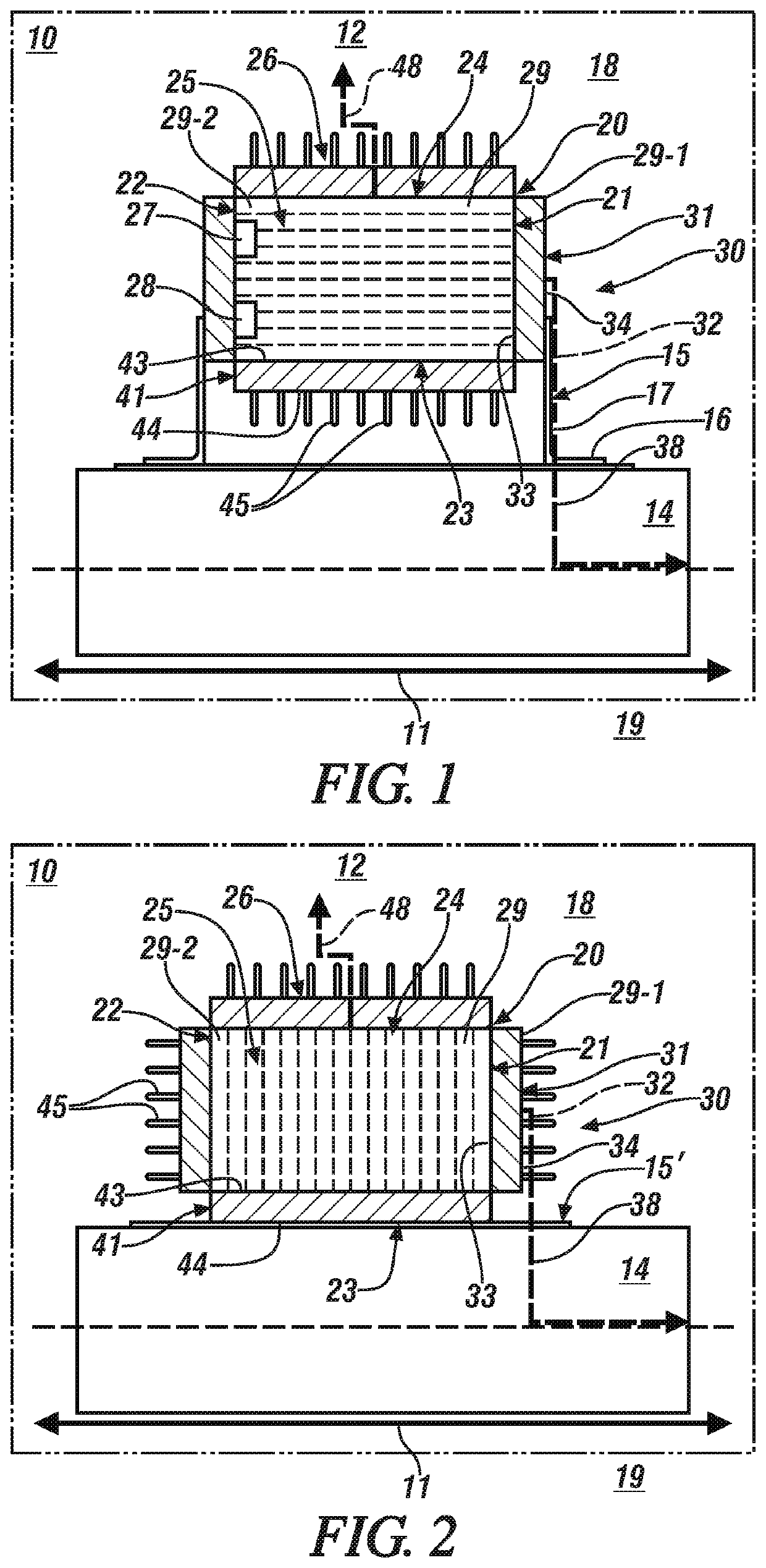
A thermal management system for an on-vehicle battery includes a battery, a first thermal element, a second thermal element, a battery mounting bracket, and a vehicle body structural element. The battery mounting bracket includes a first portion attached to the vehicle body structural element, and a second portion attached to the first thermal element. The first thermal element is attached to the first end portion of the battery, and the second thermal element is attached to at least one of the second end portion, the first and second side portions, the top portion or the bottom portion of the battery. The first thermal element is composed from a first phase-change material having a first phase-change temperature and the second thermal element is composed from a second phase-change material having a second phase-change temperature, wherein the first phase-change temperature is greater than the second phase-change temperature.

Description

INTRODUCTION[0001]DC power sources, such as high-voltage batteries, are electrochemical devices that may be employed on vehicles and elsewhere to store and release electric power that may be converted by an electric machine to generate tractive effort for vehicle propulsion. Heat may be generated by the processes of converting electric power to chemical potential energy, i.e., battery charging, and converting chemical potential energy to electric power, i.e., battery discharging.[0002]Operating a DC power source outside of a desired temperature range may reduce battery service life, and is preferably avoided. By way of example, a DC power source may employ lithium-ion technology to store electric power as chemical potential energy. Lithium-ion technology has an optimal temperature range to maximize service life of the battery, which may be in a range between 20 C and 35 C. Operation of the battery outside of this range may accelerate aging of the battery, reduce the service life of ...

Claims


Application Information

Patent Timeline
IPC IPC(8): H01M10/6569H01M2/10H01M10/0525H01M10/613H01M10/625H01M10/647H01M10/653H01M10/663B60L50/64
CPCH01M10/0525H01M2/1077B60Y2400/112H01M10/647H01M2220/20H01M2/1083H01M10/613H01M10/653H01M10/663B60R16/033H01M10/625B60Y2306/05H01M10/6569H01M10/6551H01M10/659B60L58/26B60K1/00B60K2001/005B60K11/04Y02E60/10B60L50/64B60L2240/34B60L2240/545Y02T10/70H01M50/249H01M50/209H01M50/244
Inventor NAYAK, RAVIRAJ U.FULTZ, DEREK W.DREXLER, ROBERT D.
Owner GM GLOBAL TECH OPERATIONS LLC
Learn More