
Battery control unit and battery system

a battery control unit and control unit technology, applied in the direction of parallel/serial switching, battery arrangement, transportation and packaging, etc., can solve the problems of large variation of deterioration, slow deterioration of batteries far from heat sources, rapid deterioration of batteries, etc., to reduce the variation of deterioration of a plurality of batteries

Active Publication Date: 2020-10-08
YAZAKI CORP
View PDF11 Cites 6 Cited by
  • Summary
  • Abstract
  • Description
  • Claims
  • Application Information

AI Technical Summary

Benefits of technology

The present invention provides a battery control unit and battery system that can reduce variations of deterioration in multiple batteries. By changing the depth of discharge of the batteries based on their deterioration state, the progression of deterioration can be slowed down, and more effective use of battery capacity can be achieved. The battery control unit can accurately determine the deterioration state of the battery, and the range of variation between the charge end voltage and discharge end voltage can be increased to further restrain the deterioration of the batteries. Overall, the invention allows for better control and management of battery performance.

Problems solved by technology

For example, a batten near a heat source is rapidly deteriorated, while a battery far from the heat source is slowly deteriorated.
However, if all the batteries are set to the same charge / discharge end voltage, a burden of the battery that has deteriorated may increase, thereby resulting in a larger variation of deterioration.

Method used

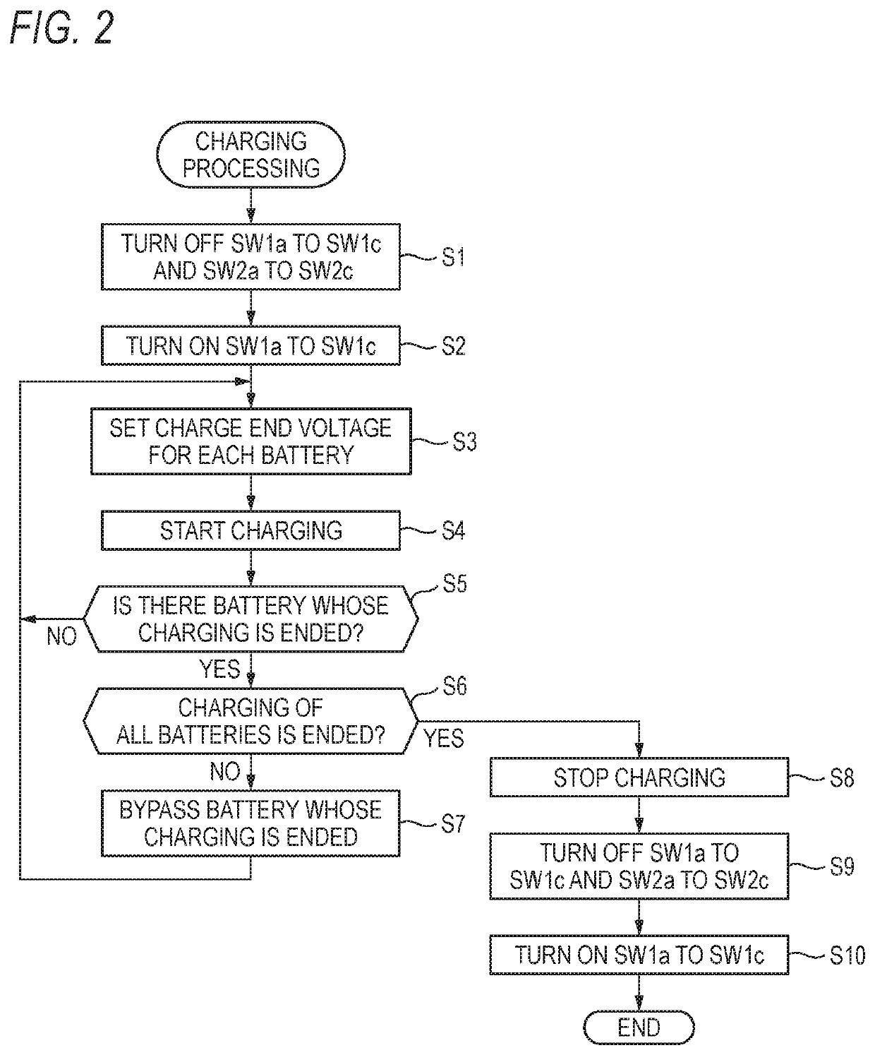
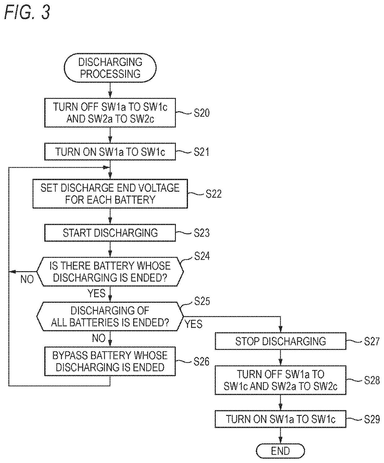

Image

  • Battery control unit and battery system
  • Battery control unit and battery system
  • Battery control unit and battery system

Examples

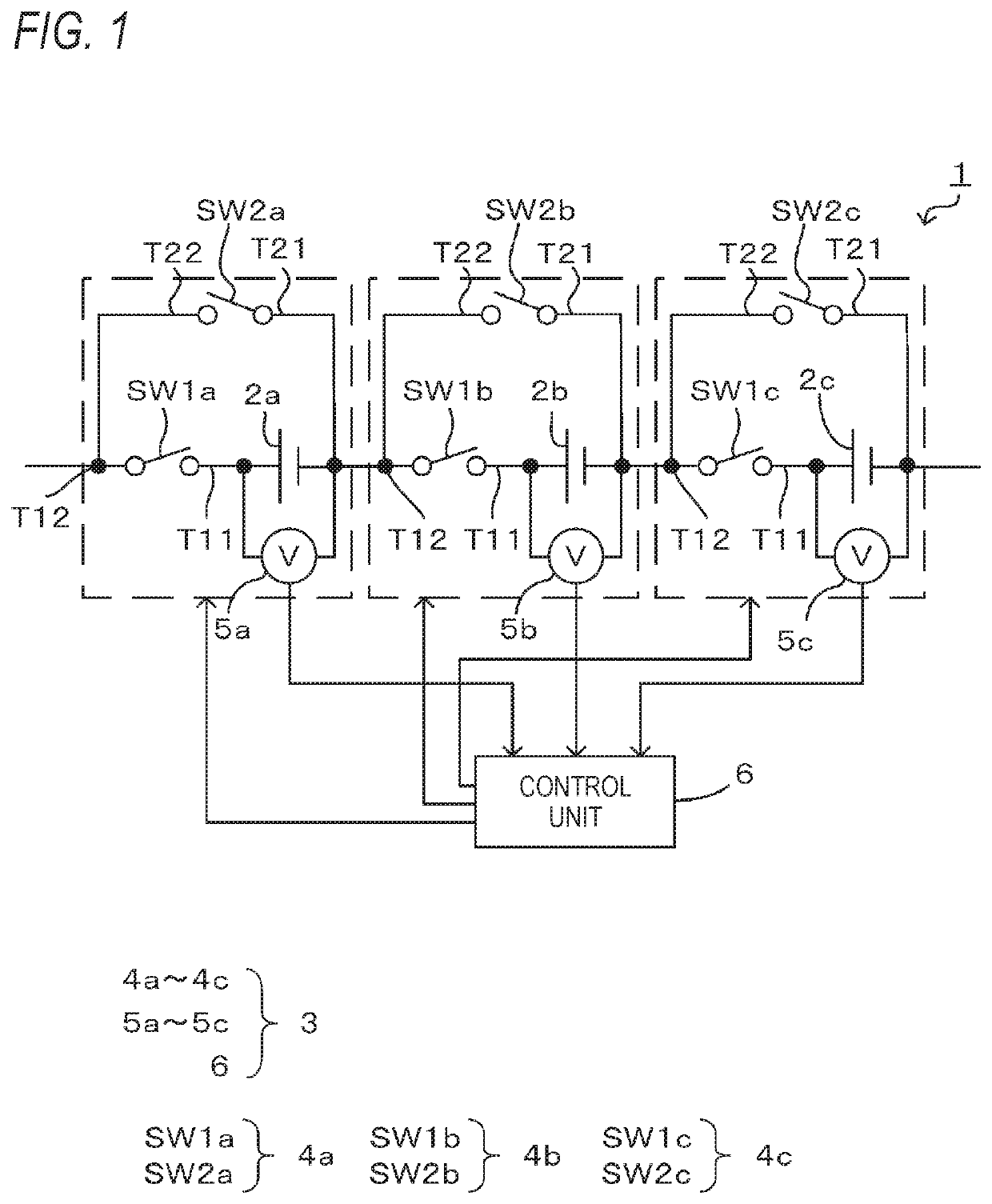

Embodiment Construction

[0026]A specific embodiment of the present invention will be described below with reference to the drawings.

[0027]A battery system shown in FIG. 1 is mounted on, for example, an EV or HEV vehicle that is driven by an electric motor and provides power source for the electric motor.

[0028]As shown in FIG. 1, a battery system 1 includes a plurality of batteries 2a to 2c and a battery control unit 3. Although an example in which the three batteries 2a to 2c are connected in series will be described in the present embodiment to simplify the description, the present invention is not limited thereto. The number of the batteries 2a to 2c may be two, or four or more as long as the number is plural. Each of the plurality of batteries 2a to 2c is a chargeable and dischargeable storage battery, and may be configured by one cell, or may be configured by a plurality of cells.

[0029]The battery control unit 3 includes a plurality of switching units 4a to 4c, a plurality of voltage measuring units 5a...


PUM


Abstract

A switching unit is provided for each of a plurality of batteries arranged in series, and switches between a connected state where the corresponding battery is connected in series with another battery and a non-connected state where series connection between the corresponding battery and the other battery is disconnected. A control unit controls the switching unit corresponding to the battery to switch to the non-connected state when it is determined that the corresponding battery reaches a charge end voltage during charging or a discharge end voltage during discharging, and determinates deterioration of the batteries. Further, the control unit changes the charge end voltage or the discharge end voltage for each of the plurality of batteries in accordance with a deterioration state of the plurality of batteries.

Description

CROSS-REFERENCE TO RELATED APPLICATIONS[0001]This application is based on and claims priority under 35 USC 119 from Japanese Patent Application No. 2019-072039 filed on Apr. 4, 2019, the contents of which are incorporated herein by reference.TECHNICAL FIELD[0002]The present invention relates to a battery control unit and a battery system.BACKGROUND ART[0003]There is a battery system configured by connecting a plurality of batteries in series as a battery mounted on a vehicle to supply electric power to a drive source or to supply electric power to an auxiliary machine. Deterioration of the plurality of batteries varies due to variations of manufacturing or variations of operating environments and so on. For example, a batten near a heat source is rapidly deteriorated, while a battery far from the heat source is slowly deteriorated.[0004]For this reason, the battery that has deteriorated at the time of charging or discharging reaches a charge / discharge end voltage first. In this case...

Claims


Application Information

Patent Timeline
Patent Type & Authority Applications(United States)
IPC IPC(8): H02J7/00
CPCH02J7/0019H02J7/0049H02J7/007182H02J7/0024H02J7/0016
Inventor ONO, CHIHIROSYOUDA, TAKAHIRO
Owner YAZAKI CORP
Learn More