
Apparatus for microfluidic flow cytometry analysis of a particulate containing fluid

a technology of microfluidic flow cytometry and particulate, which is applied in the field of apparatus for microfluidic flow cytometry analysis of particulate containing fluid, can solve the problems of difficult positioning of multiple electrode pairs around a single detection plane, difficult alignment of hydrodynamic focussing outlet, and inconvenient use of conventional planar microfluidic chips for hydrodynamic focussing apparatus, etc., to facilitate coupling the hydrodynamic focussing apparatus and greater flexibility in positioning electrod

Pending Publication Date: 2020-10-08
CELLIX
View PDF0 Cites 4 Cited by
  • Summary
  • Abstract
  • Description
  • Claims
  • Application Information

AI Technical Summary

Benefits of technology

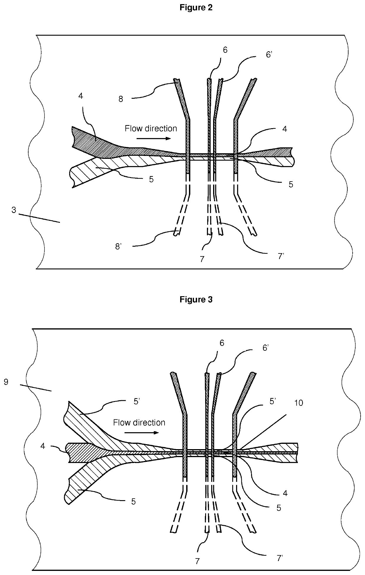
The patent describes how to sort cells using a microfluidic chip with a special design that allows for accurate cell sorting using impedance-based flow cytometry. The chip is designed to align with a hydrodynamic focusing device, which helps to keep the cells organized. The chip's design also allows for flexibility in positioning electrodes and detecting signals at different points along the chip. Additionally, the detection zone of the chip contains optical waveguides that can improve the accuracy of data points from a population of cells.

Problems solved by technology

However, conventional planar microfluidic chips are not suited for use with hydrodynamic focussing apparatus as it is difficult to align an outlet of a hydrodynamic focussing apparatus with a chip inlet disposed on the side of a planar chip.
In addition, the planar chip architecture where a longitudinal axis of the microfluidic channel runs parallel to the plane of the layers of the chip makes it difficult to position multiple electrode pairs around a single detection plane.
Furthermore, the planar microfluidic chip configuration greatly restricts the choice of possible options for the alignment of electrodes around the channel.

Method used


Image

  • Apparatus for microfluidic flow cytometry analysis of a particulate containing fluid
  • Apparatus for microfluidic flow cytometry analysis of a particulate containing fluid
  • Apparatus for microfluidic flow cytometry analysis of a particulate containing fluid

Examples


Embodiment Construction

[0082]All publications, patents, patent applications and other references mentioned herein are hereby incorporated by reference in their entireties for all purposes as if each individual publication, patent or patent application were specifically and individually indicated to be incorporated by reference and the content thereof recited in full.

Definitions and General Preferences

[0083]Where used herein and unless specifically indicated otherwise, the following terms are intended to have the following meanings in addition to any broader (or narrower) meanings the terms might enjoy in the art:

[0084]Unless otherwise required by context, the use herein of the singular is to be read to include the plural and vice versa. The term “a” or “an” used in relation to an entity is to be read to refer to one or more of that entity. As such, the terms “a” (or “an”), “one or more,” and “at least one” are used interchangeably herein.

[0085]As used herein, the term “comprise,” or variations thereof suc...


PUM


Abstract

An apparatus for microfluidic flow cytometry analysis of a particulate containing fluid An apparatus for microfluidic flow cytometry analysis of a particulate containing fluid comprises a hydrodynamic focussing apparatus for providing a focused stream of particulate containing fluid; and a microfluidic chip. The chip has a plurality of layers and comprises a microfluidic channel that extends through the chip substantially orthogonal to a plane of the layers of the chip, and is in fluid communication with the hydrodynamic focusing apparatus for receipt of a focused steam of particulate containing fluid. The chip also comprises a detection zone comprising at least one pair of electrodes in electrical communication with the microfluidic channel. At least one pair of electrodes comprise an excitation electrode coupled to an AC signal source and a detection electrode configured to detect AC impedance changes in the microfluidic channel between the electrodes resulting from particles passing between the electrodes in the microfluidic channel. Methods of sorting mammalian sperm cells according to sex is also described.

Description

TECHNICAL FIELD[0001]The invention relates to an apparatus for microfluidic flow analysis of a particulate containing fluid. In particular, the invention relates to an apparatus for microfluidic flow cytometry analysis of a cell containing fluid, and sorting of cells in a fluid containing different sub-populations of cells. The invention also relates to a method of analysis of a particulate containing fluid, and a method of sorting cells in a fluid containing different subpopulations of cells.BACKGROUND TO THE INVENTION[0002]Conventional flow cytometry makes it possible to position the cells in the center of flow channel and create uniform stream of single cells, which one-by-one pass through the focused laser beam. This is achieved by a hydrodynamic focusing setup in which the cells are injected into a capillary tube. The hydrodynamic focusing set up usually consists of two nozzles. A smaller nozzle is positioned inside the larger nozzle. Both nozzles have tapered shape. The sample...

Claims


Application Information

Patent Timeline
IPC IPC(8): B01L3/00G01N15/14
CPCG01N15/1404G01N2015/1415B01L3/502761B01L2200/0636G01N2015/1413G01N2015/149B01L3/502776B01L2300/0627B01L2300/0645B01L2200/0689B01L2300/0809G01N2015/035G01N33/4915G01N35/00029B01L2300/0816B01L2200/0652G01N2015/1019G01N15/1023G01N2015/133G01N2015/1028G01N15/149
Inventor KASHANIN, DMITRYSHVETS, IGORDICORATO, FRANCESCO
Owner CELLIX
Learn More