High-pressure mixing device with single-piece delivery duct

Active Publication Date: 2020-10-01
AFROS
View PDF0 Cites 3 Cited by
  • Summary
  • Abstract
  • Description
  • Claims
  • Application Information

AI Technical Summary

Benefits of technology

The present invention aims to provide an improved solution for high-pressure mixing devices. The new solution should reduce damaging phenomena, increase the operating life of the device, simplify construction, assembly, and operation, and make it easier and cheaper to replace the delivery duct and self-cleaning member. Additionally, the invention provides an "L-shaped" high-pressure mixing device that facilitates assembly, removal, and replacement of the delivery duct for maintenance. The device is configured to compensate for processing errors and size imprecisions, ensuring accurate positioning and orientation.

Problems solved by technology

In particular, problems relate to the three following factors: the bonding effect exerted by the reacted or reacting resins at the interface between the surfaces of fixed walls and the surfaces of movable elements on which they stratify, the leakage of resins (when still in the liquid phase they are mixed or not yet mixed or in the reaction phase) through the meatuses or the clearance of elements acting to separate and partition the resins thereof, and the wear affecting sealing elements during the operation, currently even more exacerbated by frequent cycles and high speeds.
The operation becomes more critical when such layers start accumulating on the surfaces and particularly in a differentiated way on a side of the chambers overlaying one on the other: in this case the movement of the movable scraping members is no longer able to uniformly remove polymerized layers of resin accumulating on a longitudinally-extending zone where they stratify more and more while the strong pressure causes the total scraping of the layer on the opposite side where the scraping part tends to slide with metal-on-metal contact on the surface of the duct.
On both sides of the duct the strong pressure occurring during the sliding causes such compression and friction that they generate a strong heating and then damage due to surface seizure in the metal contact zone.
Sharp-corner fronts of the self-cleaning stem 111 cannot totally remove the reacted resin by scraping the layer during the opening and closing sliding operations but they remove a part and press what remains thereof.
Such problem has been known for long and occurs in the operating life after some thousands of deliveries.
This phenomenon, which is, as previously mentioned, self-sustaining, and the direct rubbing between metal surfaces, following the heat produced, unfortunately causes, undesired scratches and seizing.
Such problem is extremely important as the damage of the surface of the delivery duct and self-cleaning stem due to seizing inevitably leads to the need to replace such an expensive and complex component as the mixing head, causing economic disadvantages due to production line interruption (necessary for the replacement operation) which lasts for not less than a few hours.
As it is impossible, or in any case extremely difficult to obtained delivery ducts with step-free zones, and with perfect axial alignment, due to too much expensive assembly requirements, the configuration of the delivery duct made of two joined pieces is the most commonly used on “L-shaped” mixing heads due to assembly rapidity and low constructive costs; however, the necessary presence of the aforesaid junction areas with inevitable resulting steps, as well as angular misalignments of axis with respect to holes, is the cause of the above discussed problems.
In the above described and discussed mixing heads, unfortunately, it is not possible to foresee and prevent asymmetric layers of hardened resins, responsible for the onset of scratches and seizure where the metal-on-metal contact occurs along the self-cleaning duct; these phenomena submit mixing heads to conditions of severe wear during operation ad inevitably force to replace the concerned pieces, composed in these cases of both head-body and extension of the self-cleaning duct, with obvious additional maintenance expenses and inevitable machine interruptions which are economically detrimental.

Method used


Image

  • High-pressure mixing device with single-piece delivery duct
  • High-pressure mixing device with single-piece delivery duct
  • High-pressure mixing device with single-piece delivery duct

Examples


Embodiment Construction

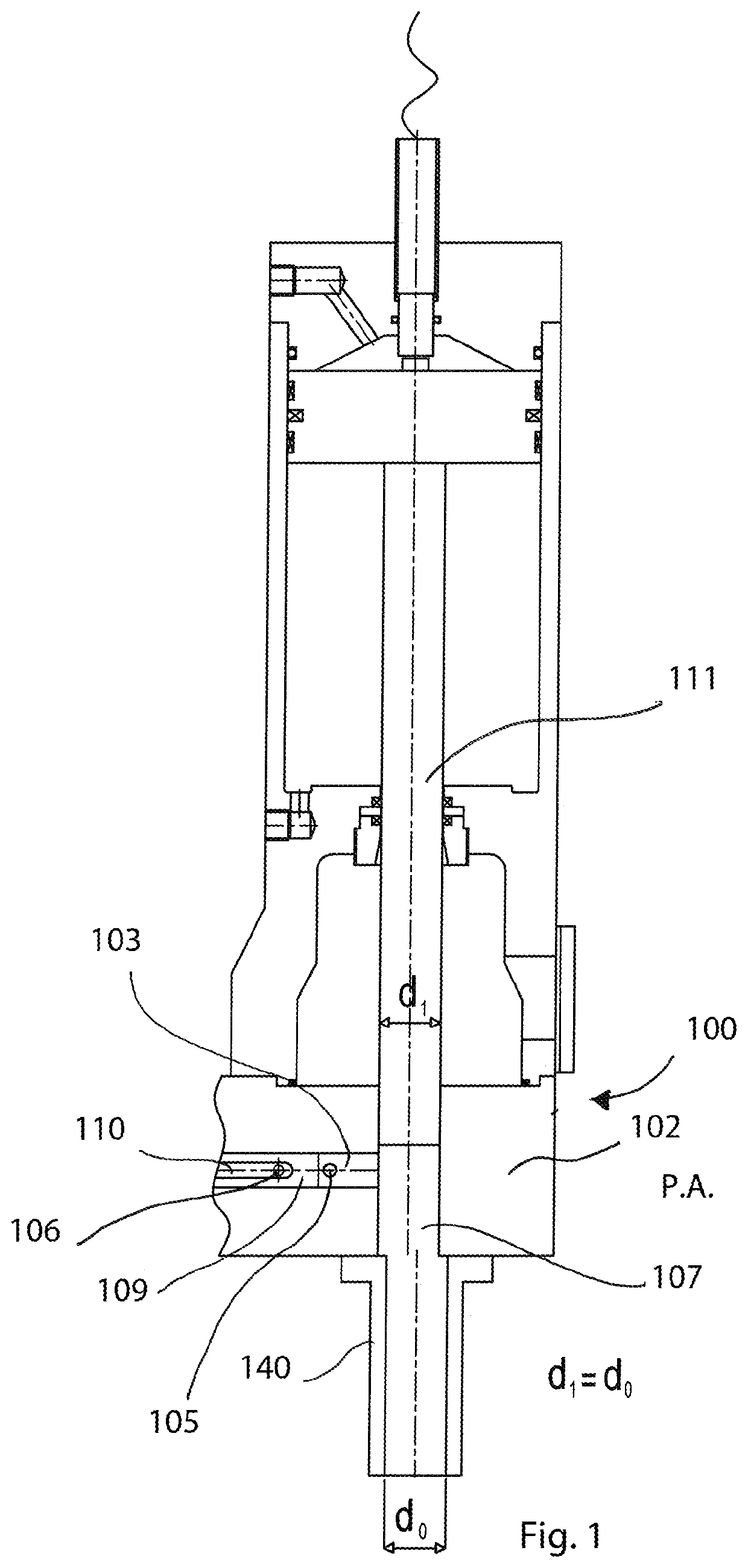
[0109]Referring to the enclosed FIGS. 6 to 45, an “L-shaped” high-pressure mixing device 1 according to the invention is disclosed, configured to mutually mix two or more liquid components or reactive resins to form a reacting polymeric mixture intended to be poured or injected to produce various objects. Polyurethane, vinyl ester, silicon and phenolic resins can be processed.

[0110]The mixing device 1 comprises a head-body 2 configured with a mixing chamber 3 having an inner cylindrical surface 4 provided with inlet openings or holes 5 and recirculation outlet openings or holes 6 for respectively inletting and recirculating liquid components or reactive resins; on the inlet openings 5 there are injectors that generate the jets of the two or more reactive resins transforming the pressure energy into kinetic energy of the jets.

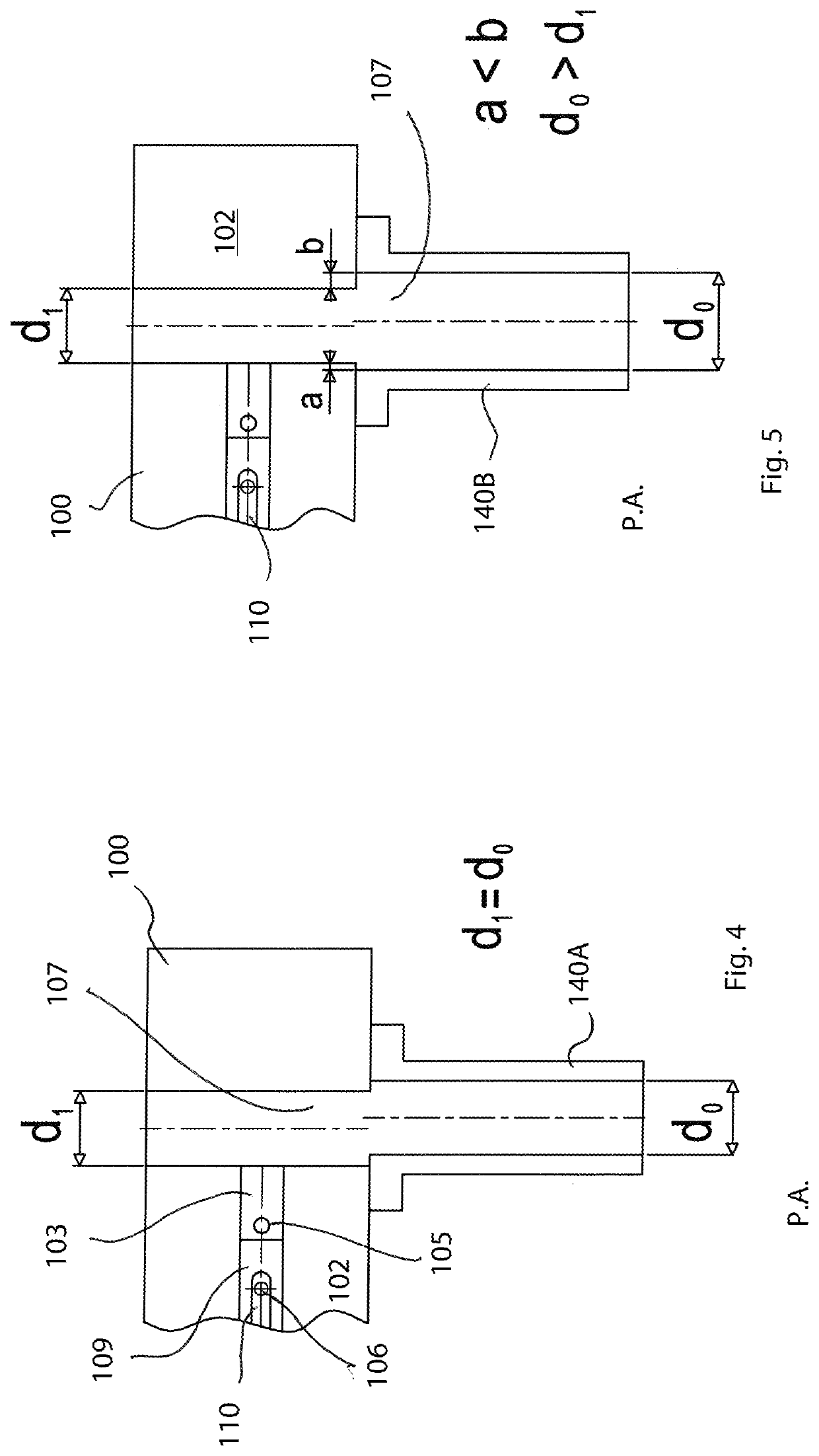
[0111]Injectors can be placed opposite to one other or with various angles that converge in a single point of the jets.

[0112]Injectors are composed of a nozzle ...


PUM

PropertyMeasurementUnit
Diameteraaaaaaaaaa
Diameteraaaaaaaaaa
Diameteraaaaaaaaaa

Abstract

A high-pressure mixing device adapted to form a polymeric mixture from the reaction of two or more reactive liquid components or resins, comprises a head-body provided with a mixing chamber having an inner cylindrical surface with inlet and outlet openings for injecting and recirculating reactive components; a duct for delivering the mixture, communicating with the mixing chamber; a valve body with recirculation longitudinal slots, sliding into the mixing chamber between a backward position in which it clears the inlet openings and enables to mix components, and an advanced position, in which the slots put inlet openings in communication with outlet openings for recirculating the reactive components; the delivery duct, of the self-cleaning type, is a single-piece tubular element, removably fastened—by means of fixing members—and can be inserted into a hole transversal to the mixing chamber passing through the head-body; the tubular element has an intermediate transversal hole aligned with the mixing chamber with a diameter greater than a diameter of the mixing chamber for compensating, while assembling, for possible inevitable errors of alignment and mutual positioning due to processing tolerances of the parts to be coupled and for avoiding protrusions of the walls of the transversal hole from forming inwardly of the mixing chamber of the head-body, protrusions that might interfere with the end the walls of the valve member during the movement in the hole passing through the thickness of the tubular element until the end of said hole leading into the delivery chamber and that extends the mixing chamber to the wall of the self-cleaning delivery duct. Between the tubular element and the pass-through hole in the head-body a gap is defined, i.e. a certain coupling tolerance with a clearance between the tubular element and the hole, enabling to insert and remove the tubular element into / from the pass-through hole. Sealing elements prevent the leakage of polymeric mixture and lubricant liquid in the aforesaid gap; analogously, between the surface of the cap and the second hole—obtained in a opposite position with respect to the hole—a respective gap with clearance is defined where an elastic or elasto-plastic sealing is interposed; the valve member, in the advanced and penetrating position into the hole of the tubular element, is separated therefrom by a gap, with a sealing member interposed therebetween; the gap prevents the metal-on-metal contact on the front part of the valve element when it enters into the intermediate hole; generally, thanks to gaps, the assembly and coupling of respective components is eased, facilitating the centering and mutual angular positioning thereof and avoiding undesired interferences; the sealing elements prevent the leakage of polymeric mixture and possible lubricant liquid in the respective aforesaid gaps.

Description

BACKGROUND OF THE INVENTION[0001]The present invention relates to a device for mixing at a high-pressure liquid polymeric components or reactive resins for forming a reacting polymeric mixture intended to be poured or injected to produce various objects. The mixing device according to the invention is able to process a polyurethane, epoxy, vinyl ester, polyester, silicon and phenolic resin.STATE OF THE ART[0002]Mixing apparatuses are known in the art, in particular high-pressure self-cleaning L-shaped mixing heads, adapted to mix polymeric components such as to obtain reacting chemical mixtures intended to be injected or delivered into a mould. Chemical mixtures originate from the impingement of at least two jets inside a circular-section cylindrical chamber referred to as mixing chamber.[0003]FIG. 1 shows a known “L-shaped” self-cleaning mixing head 100, some parts of which are also shown in FIGS. 1A, 2, 3, 4 and 5.[0004]Before being sent into the mixing chamber 103 obtained in the...

Claims


Application Information

Patent Timeline
IPC IPC(8): B29B7/76B29B7/74B01F23/47
CPCB29B7/7423B29B7/7636B29B7/7689B29B7/7668F16K3/0209B01F33/70B01F35/1453B01F35/12B01F35/71805B29B7/7647B29B7/7694B29B7/7404B29B7/7684B29C67/246B29B7/7652B29B7/7615B29B7/74B29B7/7471B29B7/802B29B7/801B29C45/18B29C45/46B29C69/00B29B7/28B01F23/47B01F25/30B01F2101/2805
Inventor VOLPATO, MARCOCORTI, MAURIZIOMOLTENI, GIORGIOFINI, FABIO
Owner AFROS
Why Eureka
Try Eureka