
Actuating device for a brake unit of an electronically controlled vehicle brake system

a technology of electronic control and brake system, which is applied in the direction of braking system, braking components, transportation and packaging, etc., can solve the problems of difficult to guide the tappet, ineffective displacement sensing, and inability to detect the displacemen

Inactive Publication Date: 2005-03-15
WABCO GMBH
View PDF30 Cites 1 Cited by
  • Summary
  • Abstract
  • Description
  • Claims
  • Application Information

AI Technical Summary

Benefits of technology

Generally speaking, in accordance with the present invention, an actuating device is provided which avoids the disadvantages of prior art actuating devices.
It is another object of the present invention to provide an actuating device that is cost effective to manufacture and assemble.

Problems solved by technology

Difficulties can arise in guiding the tappet and the component that introduces the idling stroke in such a way that minimizes friction.
Under these conditions, the slide of the displacement sensor might slip out of its receiving means in the tappet or become damaged, thus making displacement sensing impossible or ineffective.

Method used


Image

  • Actuating device for a brake unit of an electronically controlled vehicle brake system
  • Actuating device for a brake unit of an electronically controlled vehicle brake system
  • Actuating device for a brake unit of an electronically controlled vehicle brake system

Examples


Embodiment Construction

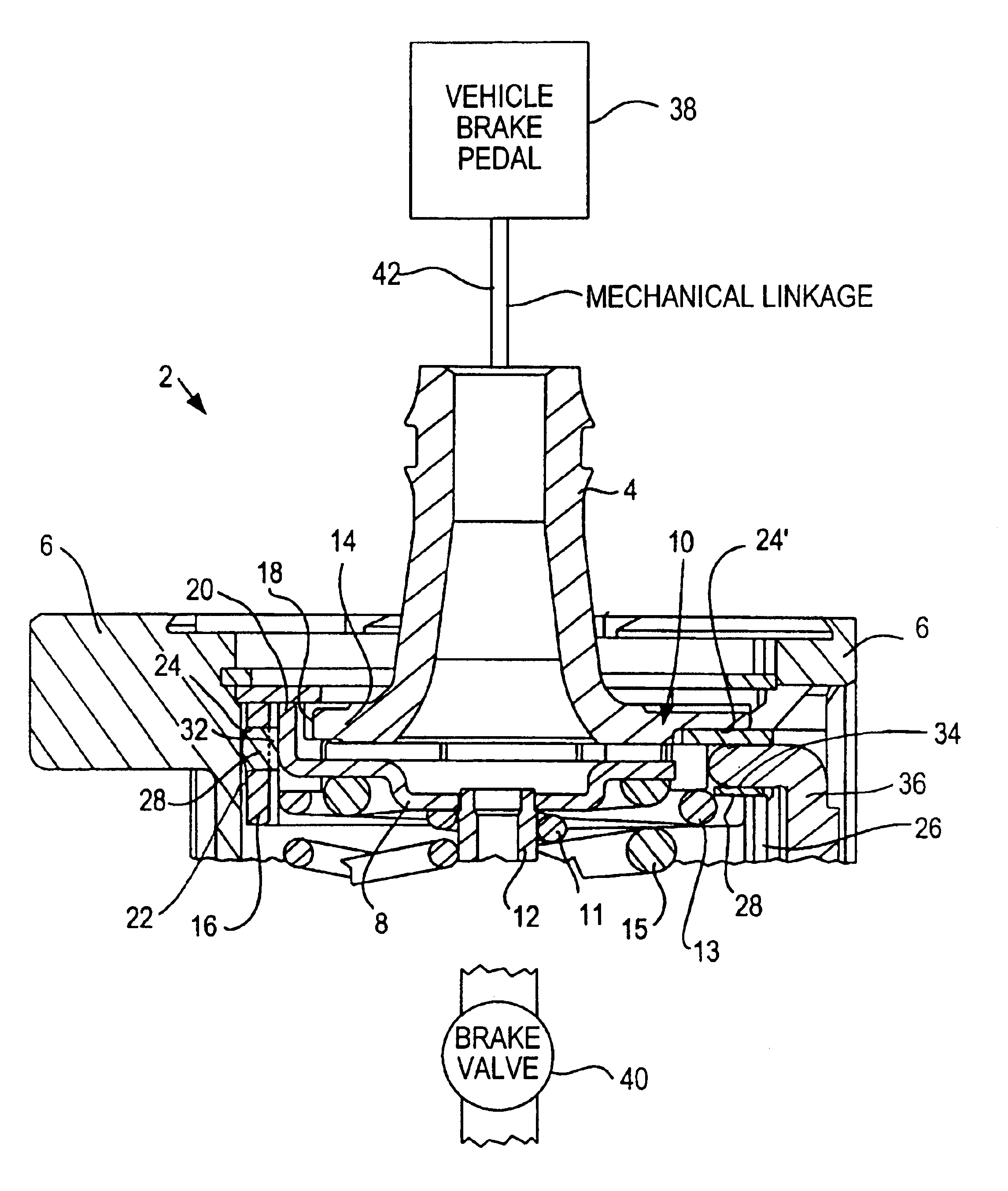
Referring now to the drawing figures where like reference numerals are used for corresponding parts, FIGS. 1-3 show various sectional views of an actuating device 2 of a brake unit of an EBS constructed in accordance with the present invention. Actuating device 2 includes a tappet 4, which is axially displaceable in a housing 6 and can be actuated by the vehicle brake pedal 38 via a mechanical linkage 42. Actuating device 2 further includes a spacer ring 8 which is axially displaceable in a widened cylindrical attachment 10 of tappet 4. A piston 12 is provided which can be moved axially by tappet 4 via spacer ring 8 (which makes a slight idling stroke) and a graduating spring 11 braced against piston 12 and against spacer ring 8. The piston 12 is actuated by tannet 4 for controlling brake valve 40. An outer return spring 13, braced against tappet 4 and against a stop, and a feeling spring 15, braced against spacer ring 8 and against a stop, are integral with the housing.

Cylindrical ...


PUM


Abstract

An actuating device for a brake unit of a vehicle EBS includes a tappet positioned in a housing of the brake unit for actuating a piston to operate a brake valve. A displacement sensor slide measures axial movement of the tappet. So that moving parts of the actuating device are guided with minimal friction and that torque acting on the tappet is compensated for, the tappet includes a cylindrical attachment having a bottom with holes and a shell, a groove on the outer surface of the shell having openings, a spacer ring in the cylindrical attachment between the tappet and the piston having projections which extend into the holes, a guide ring in the groove having raised portions on its inner surface which extend into the openings and a window on its outer surface protruding through an opening into a slit on the housing to receive the displacement sensor slide.

Description

BACKGROUND OF THE INVENTIONThe present invention is directed generally to an actuating device for a brake unit of an electronically controlled vehicle brake system.A typical electronically controlled vehicle brake system (EBS) is equipped with a purely pneumatic single circuit and with an electropneumatic circuit. The electropneumatic circuit includes, among other elements, an electronic control unit (ECU) and a brake signal transmitter with an integrated set value sensor designed as a displacement sensor, brake switch and proportional relay valve. The brake signal transmitter is connected mechanically to the vehicle brake pedal and electrically to the ECU. The brake signal transmitter (i.e., the brake unit) is provided with a tappet mechanically connected to the brake pedal and disposed in axially displaceable relationship inside the housing of the EBS brake unit. The tappet actuates a piston via a component that introduces some lost motion (i.e., idling stroke) and a spring braced...

Claims


Application Information

Patent Timeline
IPC IPC(8): B60T15/00B60T15/04
CPCB60T15/04Y10T137/86919
Inventor LESKE, OLAFCHRISTOFFERS, BERND
Owner WABCO GMBH
Learn More