Expansion valve and method for its control

a technology of expansion valve and expansion cross section, which is applied in the field of expansion valve, can solve the problems of cost-intensive construction, costly manufacture and assembly of expansion valve, etc., and achieve the effects of simple limiting of opening cross section, rapid response cooling, and enlargement of sealing diameter

Inactive Publication Date: 2011-03-29
OTTO EGELHOF GMBH & CO KG
View PDF5 Cites 2 Cited by
  • Summary
  • Abstract
  • Description
  • Claims
  • Application Information

AI Technical Summary

Benefits of technology

[0009]The object of the invention is therefore to propose an expansion valve, and also a method for controlling the expansion valve, which is cost-effective to manufacture and assemble and also to make possible simple activation for operation of the cooling medium circuit in which optimum high pressure is to the greatest extent possible present before the expansion valve.

Problems solved by technology

However, this solution has the disadvantage that a costly construction is necessary.
The activation of the solenoid valve requires the use of a pressure and temperature sensor or a control box with software in the control circuit, as a result of which this expansion valve is costly to manufacture and to assemble.

Method used


Image

  • Expansion valve and method for its control
  • Expansion valve and method for its control
  • Expansion valve and method for its control

Examples


Embodiment Construction

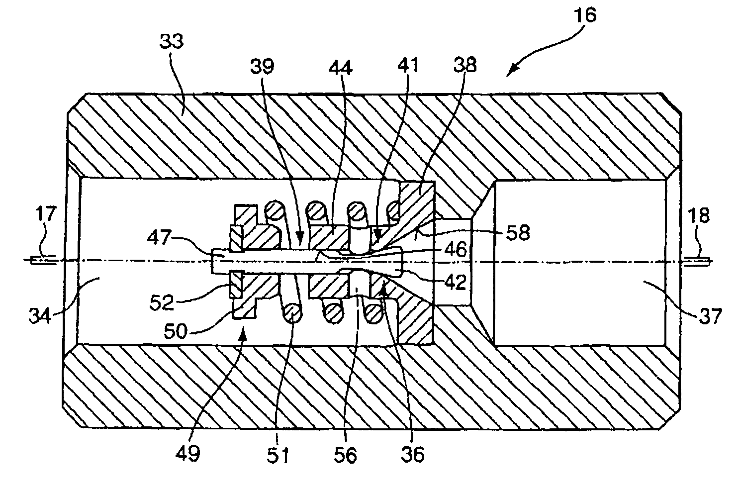
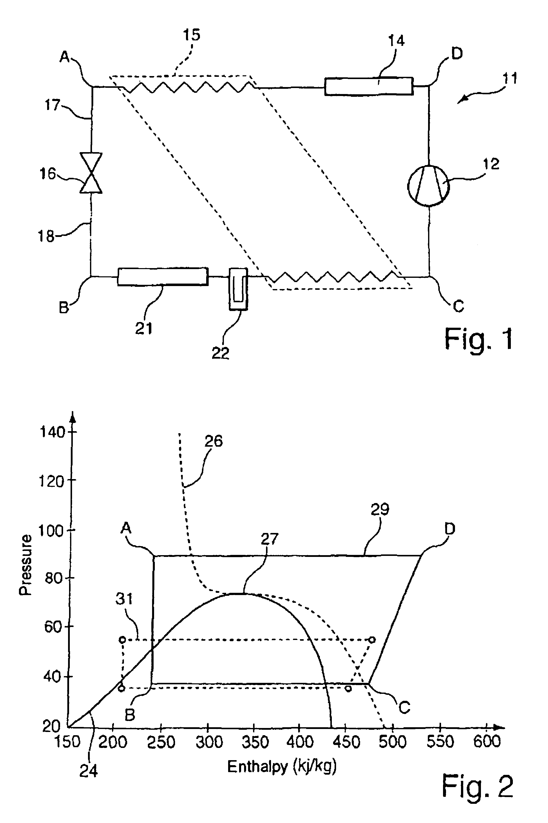
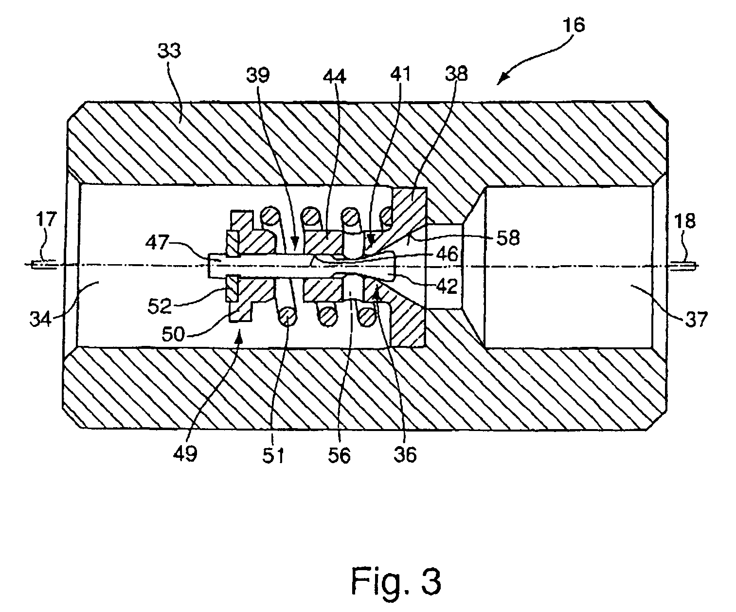
[0057]FIG. 1 illustrates a cooling medium circuit 11, which is preferably operated with CO2 as the cooling medium. A compressor 12 supplies the compressed cooling medium on the high-pressure side to an external heat exchanger 14. This communicates with the surrounding environment and gives heat off outwards. Connected downstream of this is an inner heat exchanger 15, which supplies the cooling medium to an expansion valve 16 via an inlet line 17. An inlet pressure, which may be 120 bar in summer and up to 70 bar in winter, is present on the high-pressure side before the expansion valve 16. The cooling medium flows through the expansion valve 16 and reaches the low-pressure side. On the outlet side, the expansion valve 16 has pressures of between 35 and 45 bar. The cooling medium cooled by the pressure relief passes via an outlet line 18 into the internal heat exchanger 21 and draws heat from the surrounding environment, by virtue of which the cooling of for example a vehicle interio...


PUM


Abstract

The invention relates to an expansion valve and a method for controlling an expansion valve, in which the opening and closing movement of the valve-closing element is adjusted as a function of the pressure difference which is present on the high-pressure side in an inlet opening and on the low-pressure side in an outlet opening.

Description

BACKGROUND OF THE INVENTION[0001]1. Field of the Invention[0002]The invention relates to an expansion valve and a method for its control, in particular in the form of vehicle air-conditioning systems operated with CO2 as the cooling medium which have a valve housing with an inlet opening and an outlet opening and with a valve element which is displaceable out of a valve seat of a flowthrough opening, which is arranged between the inlet opening and the outlet opening, for the flowthrough of the cooling medium.[0003]2. Related Art[0004]For cooling medium circuits of air-conditioning systems of future motor vehicles, carbon dioxide (CO2) is preferred as the cooling medium, as this substance ensures a high degree of accident safety owing to its incombustibility and moreover is not regarded as a harmful substance for the environment. In contrast to the R134a cooling circuit, operation for CO2 cooling circuits takes place in the supercritical range as well.[0005]An expansion valve which i...

Claims


Application Information

Patent Timeline
Patent Type & Authority Patents(United States)
IPC IPC(8): F25B41/04
CPCF25B9/008F25B41/062F25B2309/06F25B2309/061F25B2341/063F25B2400/0411F25B2500/01F25B2600/2505F25B41/325F25B41/33
Inventor ROBIN, JEAN-JACQUES
Owner OTTO EGELHOF GMBH & CO KG
Why Eureka
Try Eureka