Bus bar and power electronic device with current shaping terminal connector and method of making a terminal connector
a technology of current shaping terminal and power electronic device, which is applied in the direction of coupling device connection, laminated bus-bar, semiconductor/solid-state device details, etc., can solve the problems of cyclic thermal stress on semiconductor power switches, terminal debonding, fatigue cracking,
- Summary
- Abstract
- Description
- Claims
- Application Information
AI Technical Summary
Benefits of technology
Problems solved by technology
Method used
Image
Examples
second embodiment
[0056]FIG. 8 illustrates a bus bar, which includes a load terminal connector 800 in combination with supply terminal connectors 810a, 810b. The load terminal connector 800 does not overlap the supply terminal connectors 810a, 810b. Instead, the load terminal connector 800 may be disposed to one side of the supply terminal connectors 810a, 810b. The load terminal connector 800 is formed as a planar and conductive phase plate that extends from one edge 801 to an opposite edge 803, and from a facing edge 805 to an opposite edge 807. The edges 801, 803 connect the edges 805, 807 with each other.
[0057]The plate of the connector 800 includes a central opening or window 802 from which a slot 804 extends to the facing edge 805 of the phase plate (e.g., the edge that faces the supply terminal connectors). For example, the slot 804 can extend into the body of the plate of the connector 800 from the edge 805 to a larger window 802. The slot 804 divides the edge 805 into two parts or halves tha...
third embodiment
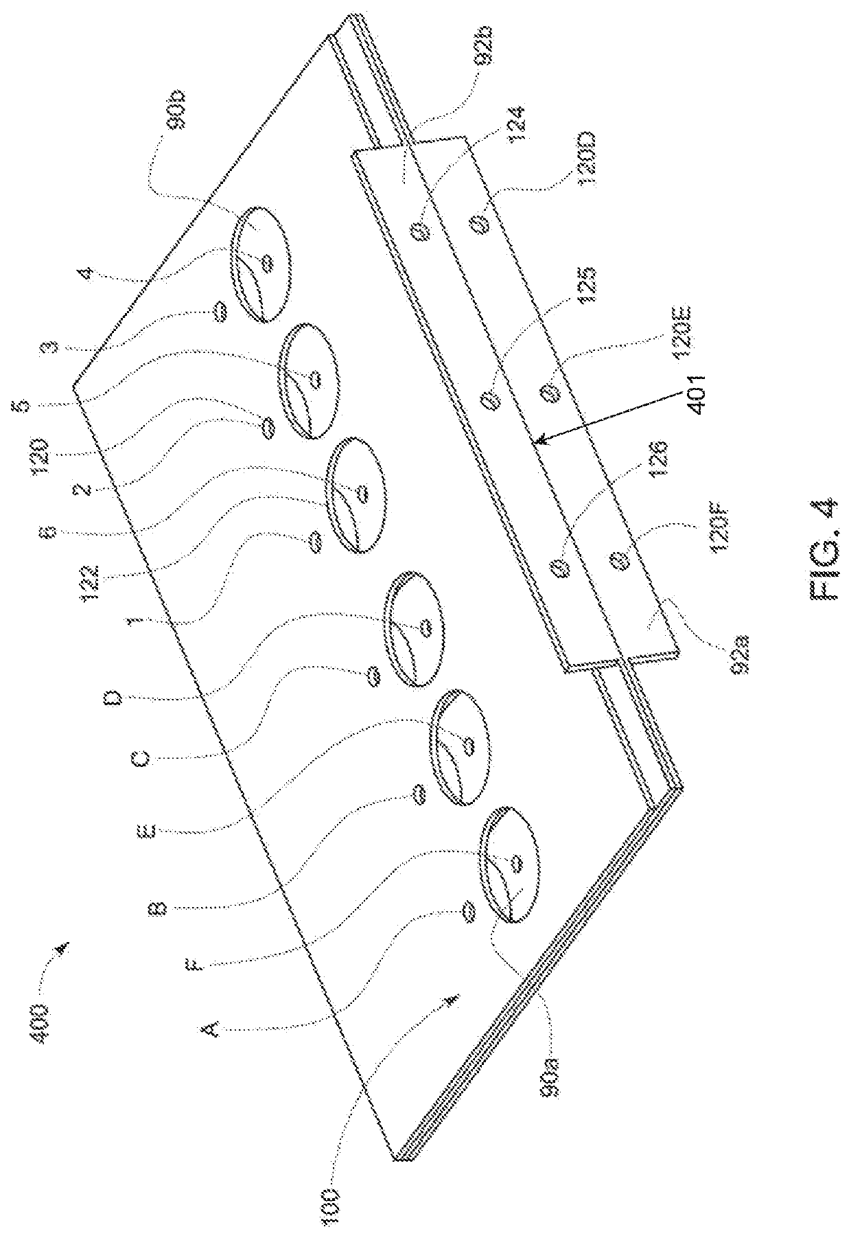
[0067]FIG. 9 shows a bus bar, which includes a similar load terminal connector 500 as shown in FIG. 5 in combination with supply terminal connectors 910a, 910b that have offset tabs 912a, 912b. The load terminal connector 500 includes a central window 502 and an open slot 504, which together impose substantially balanced conductive pathways among the plurality of pre-defined first locations A, B, C and the plurality of pre-defined second locations 1, 2, 3. The supply terminal connectors 910a, 910b include L-slots 914a, 916a, etc. that define substantially discrete conductive paths among pairs of terminal connecting holes (first locations D, E, F or 4, 5, 6 and second locations 120D, 120E, 120F or 124, 125, 126). For example, the L-slot 916a defines a substantially discrete conductive path from the hole (first location) D on supply terminal connector 910a to the hole (second location) 120D on offset tab 912a.
[0068]As in FIG. 8, the L-slots 914a, 916a, etc. define discrete conductive...
fourth embodiment
[0069]FIG. 10 shows a bus bar, which includes the same load terminal connector 800 as shown in FIG. 8, in combination with supply terminal connectors 1000a, 1000b that have central tabs 92a, 92b and V-slots 1002a, 1002b, 1004a, 1004b. The V-slots 1002a, 1002b, 1004a, 1004b define substantially discrete conductive paths among pairs of first and second locations (terminal connecting holes), e.g., the V-slot 1002b defines a path from the hole 4 on supply terminal connector 1000b to the hole 124 on tab 92b. The discrete current paths generally are orthogonal at their overlapping portions, e.g., during a commutation transient the current from hole 5 on plate 1000b to hole 125 on tab 92b flows generally orthogonal to the current from hole E on plate 1000a to hole 120E on tab 92a.
PUM
 Abstract
Description
Claims
Application Information
 - R&D
- Intellectual Property
- Life Sciences
- Materials
- Tech Scout
- Unparalleled Data Quality
- Higher Quality Content
- 60% Fewer Hallucinations
Browse by: Latest US Patents, China's latest patents, Technical Efficacy Thesaurus, Application Domain, Technology Topic, Popular Technical Reports.
© 2025 PatSnap. All rights reserved.Legal|Privacy policy|Modern Slavery Act Transparency Statement|Sitemap|About US| Contact US: help@patsnap.com


