Plastic optical fiber, plastic optical fiber cable, connector-attached plastic optical fiber cable, optical communication system, and plastic optical fiber sensor
a technology of plastic optical fiber and connector, which is applied in the direction of microstructured optical fiber, cladded optical fibre, instruments, etc., can solve the problems of increasing bending loss and difficult bending, and achieve the effects of reducing transmission loss, reducing bending loss, and reducing connection loss
- Summary
- Abstract
- Description
- Claims
- Application Information
AI Technical Summary
Benefits of technology
Problems solved by technology
Method used
Image
Examples
example 1
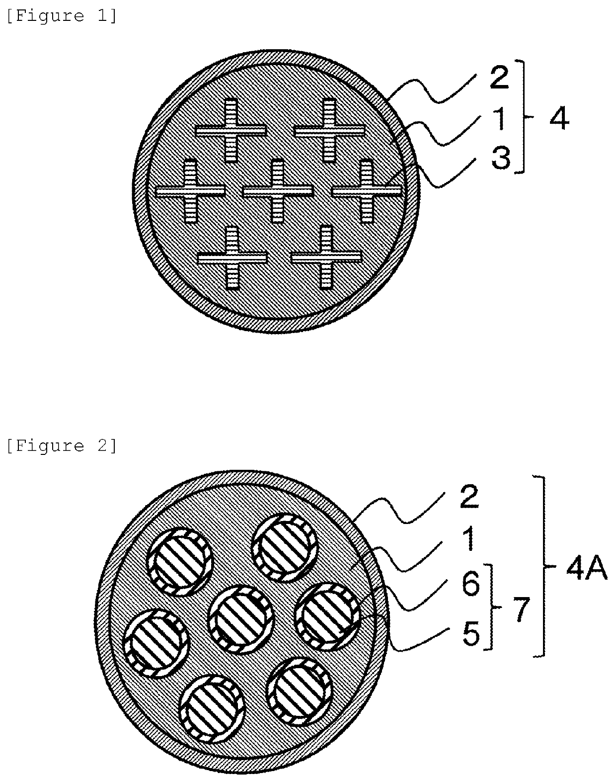
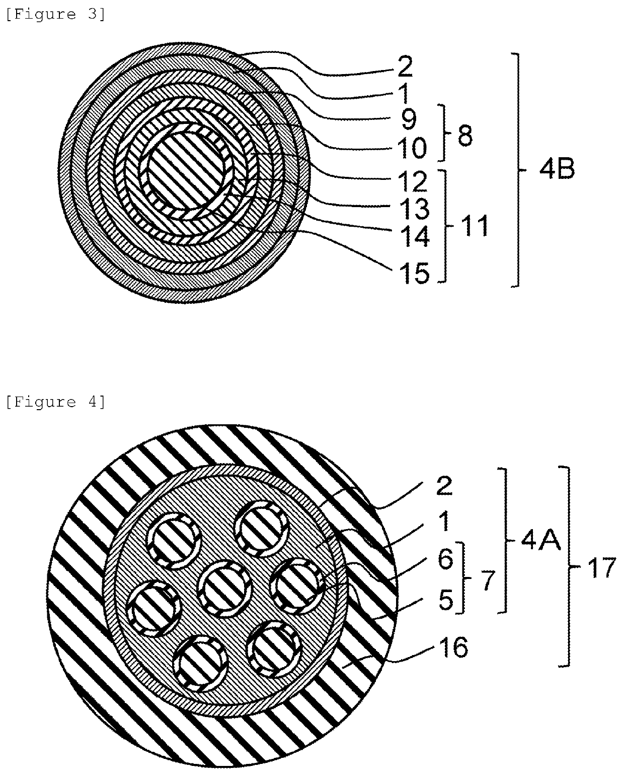
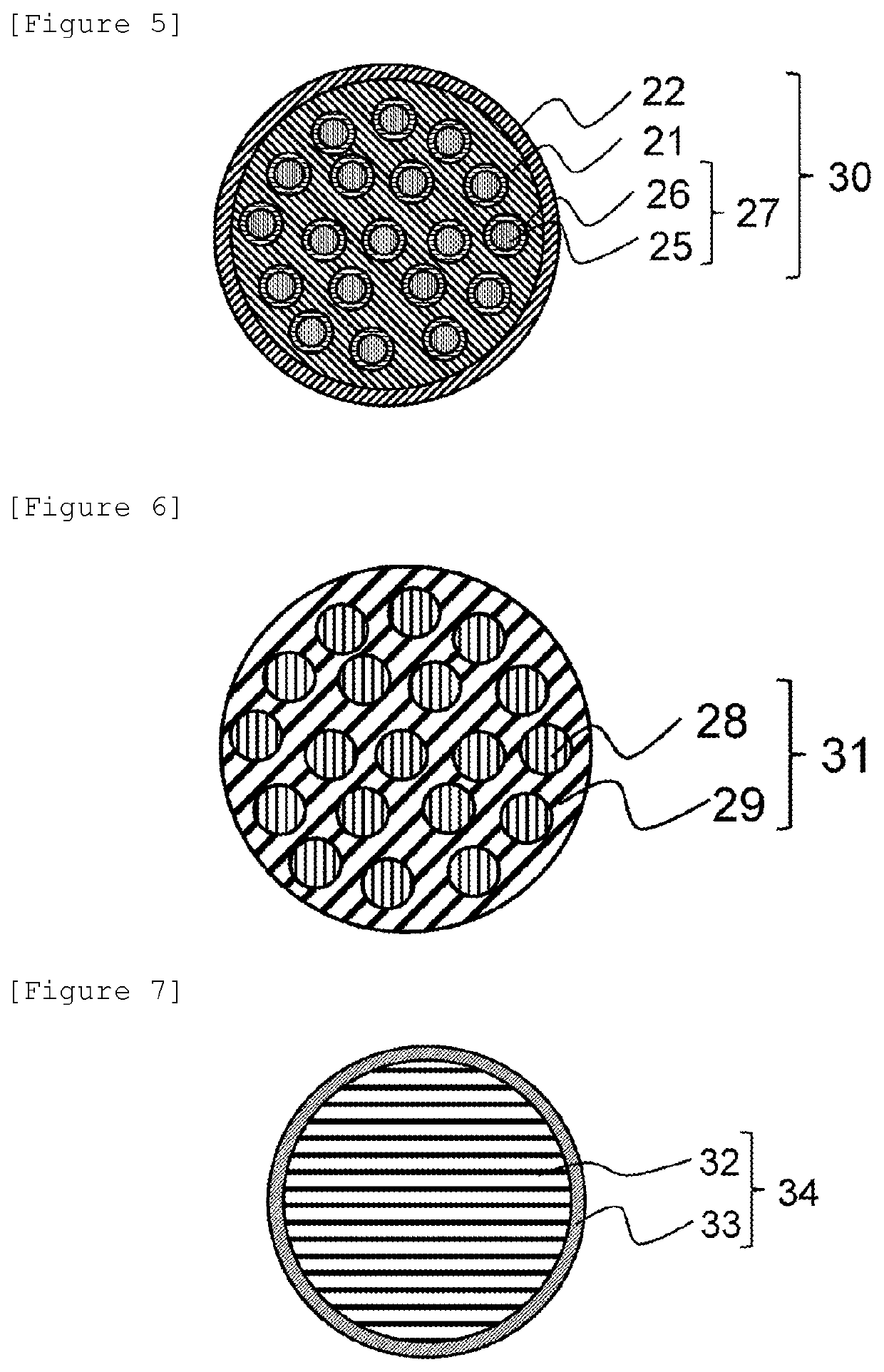
[0099]Polymethyl methacrylate (refractive index 1.491) as a material constituting a first core and second cores, and a copolymer of vinylidene fluoride, tetrafluoroethylene, and hexafluoropropene (refractive index 1.37) as a material constituting a first cladding and second claddings were respectively placed in the core resin distribution chamber and cladding resin distribution chamber of a 1-sea-19-island composite spinning die so that the flow rate ratio was core / cladding=90 / 10, and a 1-sea-19-island plastic optical bare fiber having a diameter of 1 mm was manufactured by composite spinning. The manufactured plastic optical bare fiber was coated (coating diameter 2.2 mm) with polyethylene (SUNTEC-LD M1920 manufactured by Asahi Kasei Corporation) to provide a plastic optical fiber cable. When a cross section was observed by a digital microscope (VHX-5000 manufactured by KEYENCE CORPORATION), it was confirmed that the second claddings were formed in all 19 first island portions, and...
example 2
[0100]A 1-sea-19-island plastic optical fiber cable having a diameter of 1 mm was manufactured as in Example 1 except that a fluorinated methacrylate-based polymer was used as the first cladding and the second claddings. When a cross section was observed as in Example 1, it was confirmed that the second claddings were formed in all 19 first island portions, and the first core that was a sea portion, and the second cores present in the interior of the first island portions both guided light. The plastic optical fiber cable had the structure shown in the schematic cross-sectional view of FIG. 5. The transmission loss was 148 dB / km, which was acceptable. The bending loss was 0.3 dB, which was acceptable. The connection loss was 0.9 dB, which was acceptable. The refractive index of the claddings was lower than the refractive index of the cores.
example 3
[0101]A 1-sea-19-island plastic optical fiber cable having a diameter of 1 mm was manufactured as in Example 1 except that a copolymer of ethylene, tetrafluoroethylene, and hexafluoropropene was used as the first cladding and the second claddings. When a cross section was observed, it was confirmed that the second claddings were formed in all 19 first island portions, and the first core that was a sea portion, and the second cores present in the interior of the island portions both guided light. The plastic optical fiber cable had the structure shown in the schematic cross-sectional view of FIG. 5. The transmission loss was 161 dB / km, which was acceptable. The bending loss was 0.3 dB, which was acceptable. The connection loss was 1.1 dB, which was acceptable. The refractive index of the claddings was lower than the refractive index of the cores.
PUM
| Property | Measurement | Unit |
|---|---|---|
| length | aaaaa | aaaaa |
| refractive index | aaaaa | aaaaa |
| melt flow rate | aaaaa | aaaaa |
Abstract
Description
Claims
Application Information
 - R&D
- Intellectual Property
- Life Sciences
- Materials
- Tech Scout
- Unparalleled Data Quality
- Higher Quality Content
- 60% Fewer Hallucinations
Browse by: Latest US Patents, China's latest patents, Technical Efficacy Thesaurus, Application Domain, Technology Topic, Popular Technical Reports.
© 2025 PatSnap. All rights reserved.Legal|Privacy policy|Modern Slavery Act Transparency Statement|Sitemap|About US| Contact US: help@patsnap.com


