
Noise attenuating barrier and method of installing same

a technology of noise attenuation and barrier, which is applied in the field of noise attenuation, can solve the problems of increasing the crane time for the project and therefore the installation cost, the method of installation is difficult and costly, and the installation method is difficult and costly

Active Publication Date: 2020-08-20
ENGINUITY SYST LLC
View PDF0 Cites 4 Cited by
  • Summary
  • Abstract
  • Description
  • Claims
  • Application Information

AI Technical Summary

Benefits of technology

The patent describes a noise abating wall for a noisy area. The wall includes columns with wing walls and a spandrel panel. Connectors secure the columns and panels together in a vertical orientation. The connectors are designed to bias the panels and columns together to create a wall that reduces noise. The panels can be precast and the columns formed using precast concrete. The panels and wing walls are supported in a vertical orientation. The technical effect of this invention is to provide a wall that reduces noise in a noisy area.

Problems solved by technology

This method of installation is difficult and costly because it is difficult to temporarily support the large weight of the full-length column section while also maintaining the plumbness until the CLSM has sufficiently cured to permanently support the one-piece column section.
This usually requires the use of a portable crane during the full installation time of a column section which increases crane time for the project and therefore the cost of installation.
This also requires the field crew to be more exacting in their setting of the column, adding more time per column installation, since any variance in plumbness or location can potentially impact the fit up of the remainder of the wall system.
Either option requires handling of the posts during the construction of the drilled pier which can lead to paint / galvanizing chipping and defects to the steel section.
In addition, since the contracts of noise abatement wall projects are typically held by the precast manufacturer / contractor for the precast concrete panel portion of the wall, the rolled steel portion of the project is typically completed by a steel fabricator working as a subcontractor to the precast manufacturer / contractor, typically leading to an additional markup on the pricing of the steel portion of the materials of the project.
Still further, the rolled steel column section is oversized in the design of this system compared to the steel column size needed to support the actual design loads on the wall system (rolled steel sections are not custom made for each project but instead are standard steel industry sizes, often resulting in use of sizes which are larger than required for the noise abatement wall).
Such steel bent plates are typically spaced no further than 3′-0″ to 4′-0″ on center vertically for the exposed above grade height of the column, adding to the fabrication costs of the column section.
Further, when an installation of noise abatement walls with one-piece rolled steel columns requires a corner or kink where the wall cannot be straight, the fabrication and welding of the required additional bent plates can add significant cost and require more exact placement in the field to ensure the precast panels will fit and be aligned as required.
Still further, exposed steel columns are susceptible to corrosion thereby reducing their effective structural properties and strength over time, and thus the steel columns are commonly required to be hot dipped galvanized.
This galvanic coating can help maintain the longevity of the system, but even then, the coating can be damaged during construction and sustained exposure and eventually fail, allowing corrosion to occur and requiring field maintenance over time to protect the rolled steel columns and adding additional cost to the wall.
As with the other configurations requiring anchor rods, construction and installation is costly since it requires a number of field construction tasks in order to accomplish the setting of the two-piece column section to form a single full height column.
In addition, this configuration requires the added cost of a concrete subcontractor, and reinforcing supplier / subcontractor for accomplishing the concrete portion of the work, as well as typically also requiring a steel fabricator working as a subcontractor to the precast manufacturer / contractor.
Further, as with one-piece rolled steel columns, the rolled steel column section is oversized relative to the need due to use of standard sizes, increasing material costs, and also necessitating use of multiple steel bend plates to properly secure wall spandrel panels to the columns, also adding material costs as well as adding fabrication costs Still further, cost adding galvanic coating is required in addition to the cost of field maintenance over time.
In addition to the problematic aspects of pier foundations of prior noise abatement walls, problems have existed with the precast concrete spandrel panels which span horizontally between column locations and forms the noise abatement wall.
These notches require custom spandrels, slowing and complicating the spandrel panel manufacturing and fabrication and increasing costs.
In addition, typical wall project specifications for state transportation departments require that the wall be completely solid with no light or smoke able to penetrate through the wall system, which necessitates the costly manual application of a foam backer rod and fire retardant “structural caulk” for the full height of the column at the backside of the precast concrete spandrel panel at the interface between the panel and the column.
Height restrictions (e.g., overhead power lines and overhead bridges) limiting the accessibility to lift and set precast spandrel panels from up and above the top of steel posts can also complicate and increase costs.
However, this requires clip angles to be welded or bolted on in the field after the panels are installed and for the contractor to provide temporary shoring of the panels until the portion of the missing back flange of the steel posts is installed.
Sometimes both options are used depending on the height restrictions or abilities of the contractor to lift and install the panels, all of which increase costs and time of installation.

Method used


Image

  • Noise attenuating barrier and method of installing same
  • Noise attenuating barrier and method of installing same
  • Noise attenuating barrier and method of installing same

Examples


Embodiment Construction

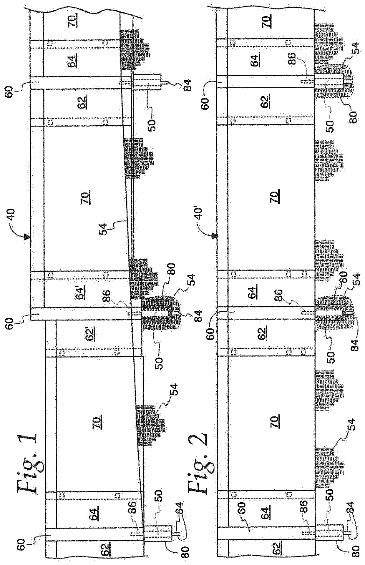
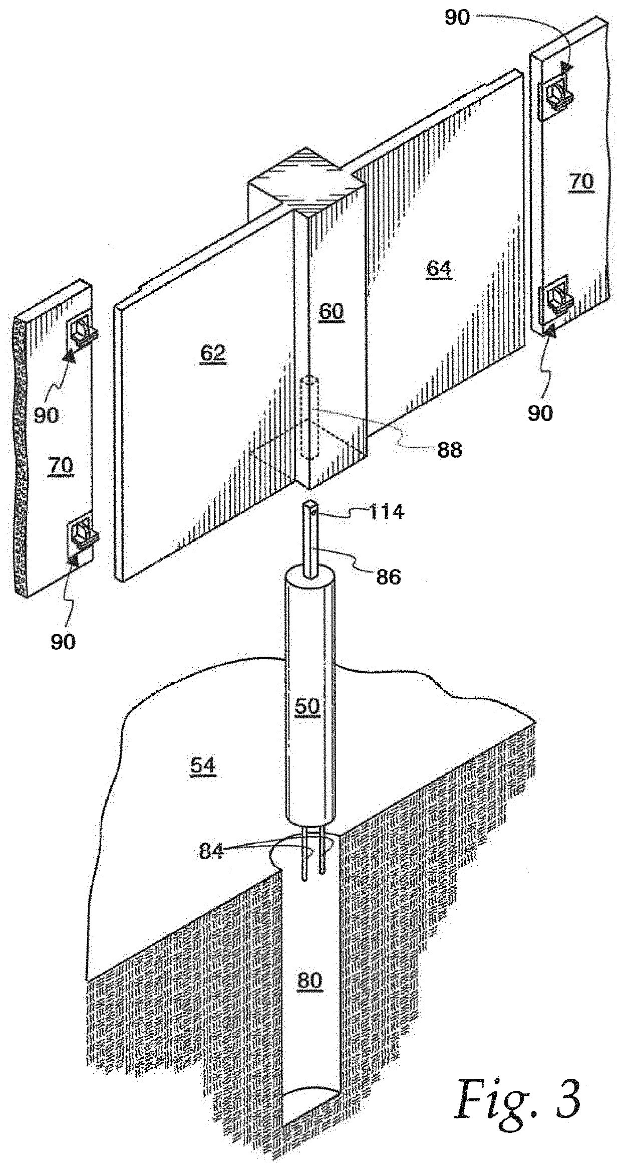
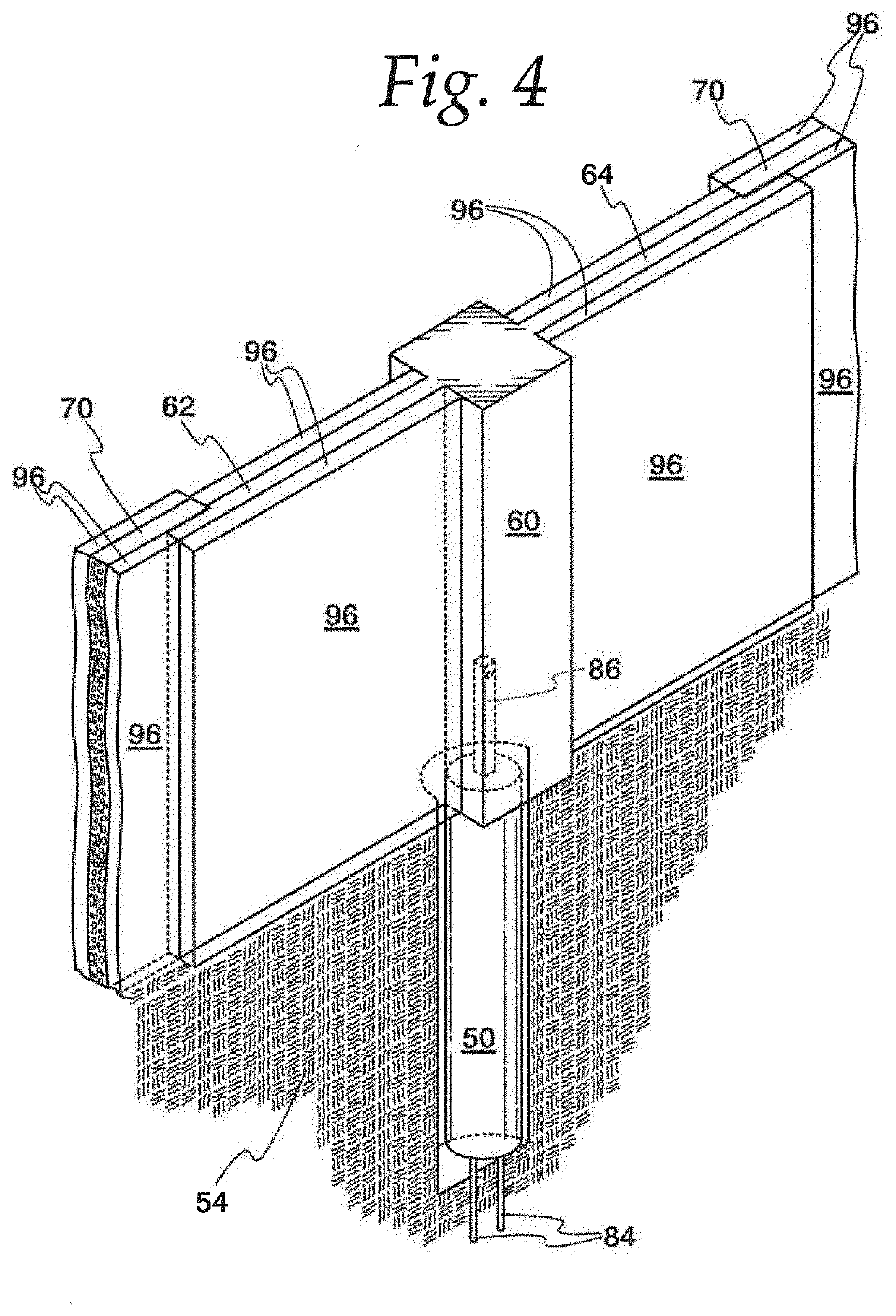
[0046]New and advantageous noise attenuating walls or barriers 40 are illustrated in FIGS. 1-2. In one form as illustrated in those figures, and as discussed in greater detail hereafter, the walls 40 include a plurality of spaced precast concrete piers 50 secured in the ground 54, each pier 50 supporting a column 60 which is precast monolithically and integrally with a pair of wing walls 62, 64 cantilevered on the column 60. A spandrel panel 70 on opposite sides overlaps with and is secured to the wing walls 62, 64 of adjacent columns to form the wall 40. The height of the spandrel panels 70 may be of any required height depending on the environmental requirements (with suitable piers 50 and columns 60), including up to at least thirty (30) feet.

[0047]The wall 40 shown in FIG. 1 is installed on uneven ground 54, and the wall 40′ shown in FIG. 2 is on even ground 54′. For uneven ground as in FIG. 1, the wing walls are secured at different heights to the sides of the column 62 (see, e...


PUM


Abstract

A noise abating wall including piers with integral column members, columns each including two laterally extending wing walls, and a spandrel panel. The piers are secured in spaced ground holes with column members extending vertically from the pier securing the columns in a vertical orientation with the wing wall outer sides having a selected spacing from one wing wall of an adjacent column. The spandrel panels are wider than the selected spacing of wing walls of adjacent columns whereby the spandrel panel sides overlap the sides of adjacent wing walls. First connectors on the spandrel panel front face adjacent both of the panel opposite sides and second connectors on the wing wall rear faces adjacent the wing wall outer sides connect together to secure the overlapping walls and spandrel panels in substantially face to face contact.

Description

CROSS-REFERENCE TO RELATED APPLICATIONS[0001]Not Applicable.FEDERALLY SPONSORED RESEARCH OR DEVELOPMENT[0002]Not Applicable.MICROFICHE / COPYRIGHT REFERENCE[0003]Not Applicable.FIELD OF THE INVENTION[0004]The present invention relates to noise attenuation and more particularly to barriers blocking noise emanating from noisy areas.BACKGROUND OF THE INVENTION[0005]Noise abatement walls or noise barriers are known, with extensive use of noise walls having begun in the United States after noise regulations were introduced in the early 1970's. This coincided with the suburban sprawl which resulted in the increased need to protect individuals with sensitive land use from the increased noise pollution. Noise Abatement Walls are also effective in large high density cities where residential developments are located adjacent to highway systems.[0006]Noise abatement walls typically incorporate vertical column elements constructed of either precast concrete or standard rolled steel sections. The ...

Claims


Application Information

Patent Timeline
Patent Type & Authority Applications(United States)
IPC IPC(8): E01F8/00E04H17/16G10K11/162
CPCE01F8/0023G10K11/162E04H17/16E01F8/0017G10K11/16
Inventor TRYON, MARK ADAMMYKET, ALLAN THOMAS
Owner ENGINUITY SYST LLC
Learn More