Electronic Control Unit

a technology of electronic control unit and electronic control unit, which is applied in the direction of battery/fuel cell control arrangement, safety/protection circuit, transportation and packaging, etc., can solve the problems of increasing the size of the electronic control unit, requiring a large number of elements, and requiring a high breakdown voltage. , to achieve the effect of reducing the number of components, and simple circuit configuration

Active Publication Date: 2020-08-20
HITACHI ASTEMO LTD
View PDF0 Cites 0 Cited by
  • Summary
  • Abstract
  • Description
  • Claims
  • Application Information

AI Technical Summary

Benefits of technology

[0015]According to the present invention, since the first voltage limiting element limits the voltage at the first power terminal side to the predetermined negative voltage, and the second voltage limiting element limits the voltage at the second power terminal side to the predetermined negative voltage, it is possible to prevent the first and / or second power terminals from being applied with excessive negative voltages, to thereby protect the internal circuit from a negative surge. Furthermore, since the limit voltage of the first voltage limiting element is greater than the limit voltage of the second voltage limiting element, it is possible to prevent a decrease in input terminal voltage, which might cause shutdown of the power supply IC. Furthermore, since the second diode provided in the current path extending from the second power terminal to the power supply IC is shared by the protection paths to the first and second power terminals, it is possible to reduce the number of components.
[0016]Thus, it is possible to achieve a simple circuit configuration having the surge protection function and the reverse input protection function, equivalent to those in conventional art.
[0017]Therefore, by reducing the number of components, and by reducing the mounting area on the circuit board, it is possible to reduce the size. Furthermore, since the surge protection is performed by using the first and second voltage limiting elements to prevent any section from being applied with a high voltage, it is not necessary to use an expensive, high breakdown voltage element, resulting in a decrease in cost.

Problems solved by technology

Thus, an expensive element with a high breakdown voltage is required.
Furthermore, when the reverse input protection FET and a switching FET for use with the reverse input protection FET, are used for protection from a negative surge voltage, this configuration requires a large number of elements, including those for peripheral circuits for controlling these FETs.
This causes an increase in size of the electronic control unit and an increase in product cost.

Method used


Image

  • Electronic Control Unit
  • Electronic Control Unit
  • Electronic Control Unit

Examples


first embodiment

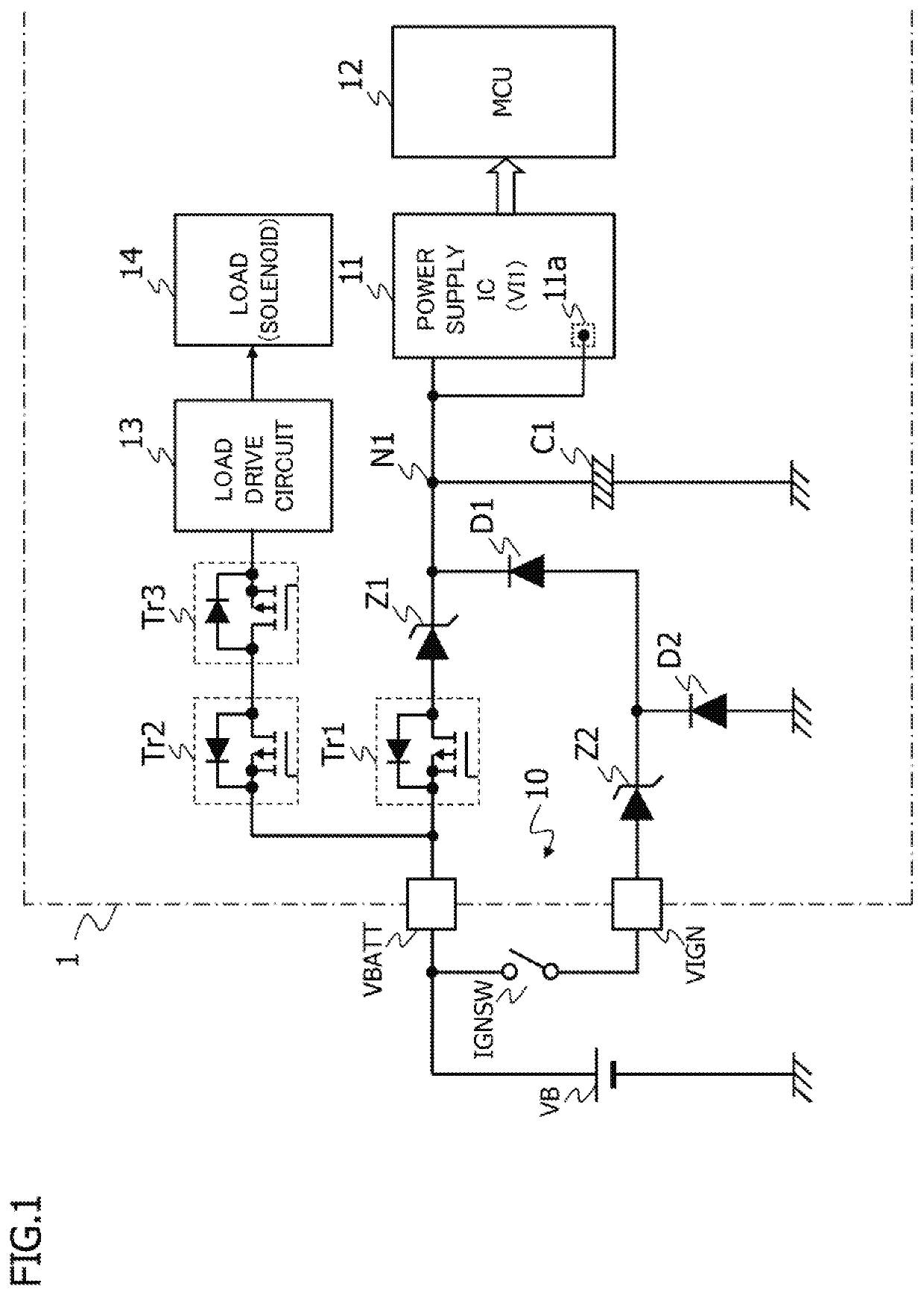
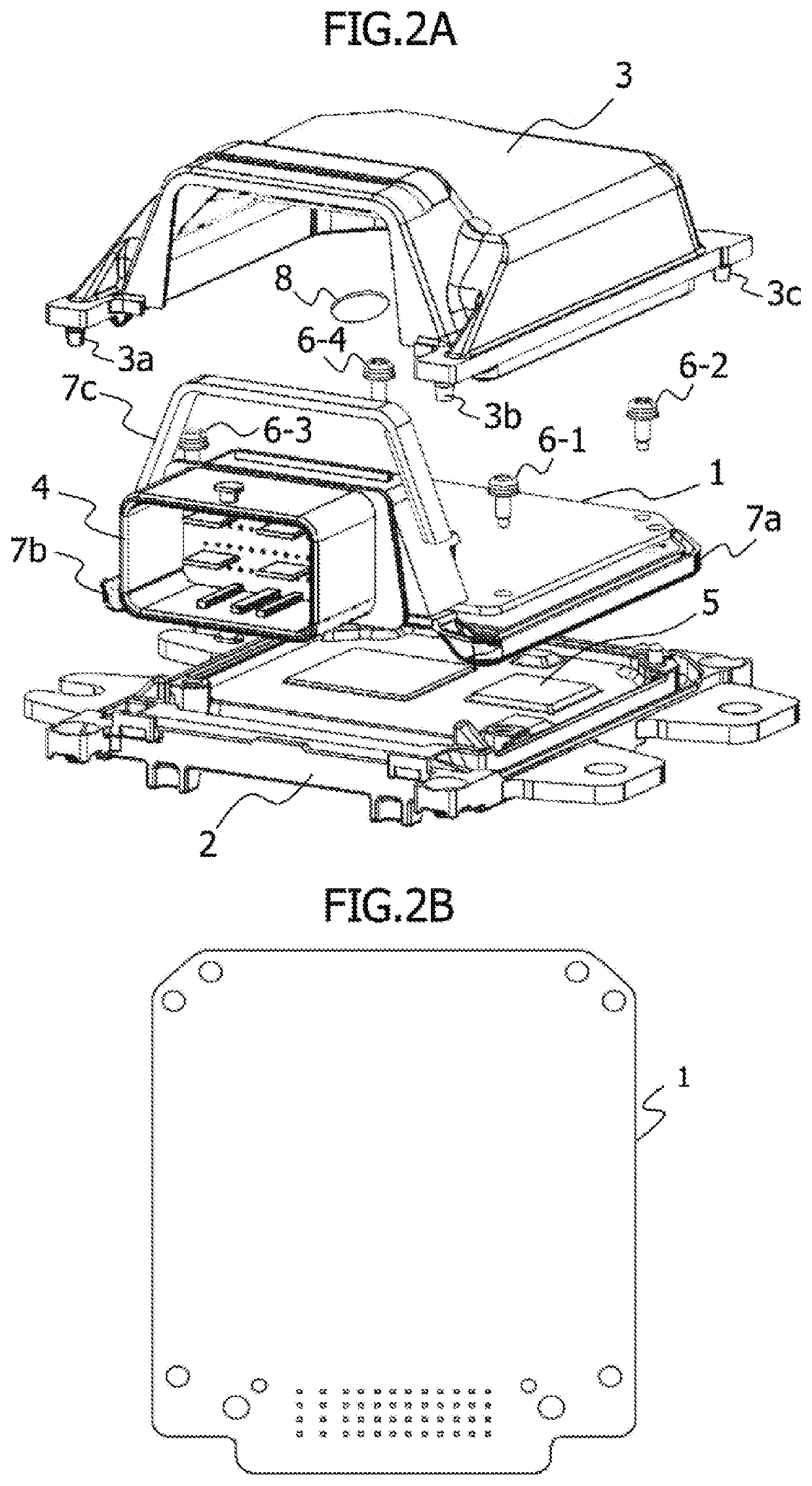
[0026]FIG. 1 shows a circuit configuration of a power input unit and its vicinity in an electronic control unit according to a first embodiment of the present invention. FIGS. 2A and 2B show a schematic configuration of an electronic control unit for a continuously variable transmission (CVT), to which the electronic control unit of the present invention is applied. As shown in FIG. 2A, the electronic control unit includes a circuit board (PCB) 1, and a metal base 2 and a resin cover 3 between which circuit board 1 is placed. Circuit board 1 is accommodated in a space defined by metal base 2 and resin cover 3, and has a planar shape, as shown in FIG. 2B. Although not shown in the drawings, various electronic components are mounted on circuit board 1, and a connector 4 for electrical connection with external devices is provided such that connection portions are exposed from a side surface of resin cover 3.

[0027]Metal base 2 is made of a metal material superior in heat-radiating prope...

second embodiment

[0052]FIG. 6 shows a circuit configuration of a power input unit and its vicinity in an electronic control unit according to a second embodiment of the present invention. In the second embodiment, single common MOSFET Tr1 is used, instead of MOSFETs Tr1 and Tr2 in the first embodiment. That is, MOSFET Tr2 is omitted, and thus, the source of MOSFET Tr1 is connected to power terminal VBATT, and the drain of MOSFET Tr1 is connected to the anode of Zener diode Z1 and the drain of MOSFET Tr3.

[0053]Other configurations are similar to those in FIG. 1. The same components are denoted by the same reference symbols, and their descriptions will be omitted.

[0054]In the abovementioned configuration, when the voltage applied to power terminal VIGN is denoted as Vign, the forward voltage of Zener diode Z2 is denoted as Vfz2, the forward voltage of diode D1 is denoted as Vfd1, the Zener voltage of Zener diode Z1 is denoted as Vz1, and the maximum drain-source rated voltage of MOSFET Tr3 is denoted ...


PUM

PropertyMeasurementUnit
voltageaaaaaaaaaa
voltageaaaaaaaaaa
voltageaaaaaaaaaa

Abstract

The ECU includes first and second power terminals, first and second voltage limiting elements, first and second diodes, and a power supply IC. A voltage is applied to the first power terminal from a battery, and a voltage is applied to the second power terminal from the battery via a start switch. The first voltage limiting element is provided between the first power terminal and an input terminal of the power supply IC. The cathode of the first diode is connected to the input terminal of the power supply IC. The second voltage limiting element is provided between the second power terminal and the anode of the first diode. The cathode of the second diode is connected to the anode of the first diode, and the anode is grounded. A limit voltage of the first voltage limiting element is greater than a limit voltage of the second voltage limiting element.

Description

TECHNICAL FIELD[0001]The present invention relates to in-vehicle electronic control units having a surge protection function for protecting a power input unit from a negative surge.BACKGROUND ART[0002]Conventionally, an in-vehicle electronic control unit is provided with a reverse input protection circuit to protect an internal circuit from a reverse input caused by a reverse connection of a battery terminal due to human error, or the like. Furthermore, a surge protection circuit is provided in a power input unit, to protect the internal circuit from a surge voltage generated by a switching operation, or the like, when driving a load.[0003]For example, Patent Document 1 discloses an in-vehicle control unit that includes a reverse input protection circuit including MOSFETs, and that protects the MOSFETs when a surge voltage occurs. According to the disclosure of Patent Document 1, even if a voltage of the battery drops to near an operable limit voltage of an electronic control unit (...

Claims


Application Information

Patent Timeline
Patent Type & Authority Applications(United States)
IPC IPC(8): B60L58/12H02H11/00H02J7/00
CPCH02J7/0034B60L58/12H02H11/003H02H3/003H02H3/18H02J1/08H02J7/00H02J7/00308H02J2310/48Y02T10/70B60R16/033H02J7/0045H02M1/32
Inventor KATABUCHI, HIROKI
Owner HITACHI ASTEMO LTD
Why Eureka
Try Eureka