Polarity-reversal protection arrangement, method for operating the polarity-reversal-protection arrangement and corresponding use

a protection arrangement and polarity-reversal technology, applied in the direction of electric/fluid circuits, instruments, vehicle components, etc., can solve the problems of inability to combine the two, and inability to control the feedback into the on-board power system

Active Publication Date: 2020-08-13
CONTINENTAL TEVES AG & CO OHG
View PDF9 Cites 2 Cited by
  • Summary
  • Abstract
  • Description
  • Claims
  • Application Information

AI Technical Summary

Benefits of technology

[0023]The embodiments advantageously make it possible to provide both modes and to make them usable. T two modes are operated alternately, such that metered feeding of energy back into the on-board power system is performed. By virtue of metered feedback, a certain safety level of the control device or of the vehicle is able to be guaranteed at all times, taking into account predefined limits. The thermal losses within the control device are therefore able to be reduced, which enables a more compact and more robust product design.
[0024]A further advantage is that the pins on the IC housing of an ASIC are able to be used jointly. The proposed interconnection means in particular that fewer pins are required for connection, as a result of which space and resources are able to be saved at this point.
[0025]In one or more embodiments, a node point is arranged in the connection between the amplifier circuit and the output driver stage and the polarity reversal protection arrangement has a resistor that is connected to the node point and one of the connection nodes, in particular the connection node to the on-board power system. The resistor makes the polarity reversal protection arrangement more durable by protecting the entire arrangement against “polarity reversal”, that is to say ISO pulses, load dump and any type of destructive electrical pulses on the on-board power system. This results in improved robustness of the arrangement against destruction.
[0028]Use is made in this case of a monitoring circuit that is accommodated in a component together with the switch circuit. The development therefore makes it possible to use the monitoring circuit not only for monitoring the switch circuit but also for the amplifier circuit. This advantageously means that no additional components, such as for example a further monitoring circuit for monitoring the amplifier circuit, are necessary. The monitoring circuit comprises a test function and / or a diagnostic function. By way of example, the circuits may be monitored for faults, for example during ongoing operation. However, predefined tests may also be performed, these giving an indication with regard to faults in the circuits. The data are evaluated, for example by a microprocessor, such that a fault message is able to be output. The fault message is able to be accessed using the diagnostic function or the functions of the monitoring circuit are able to be controlled by way of the diagnostic function.
[0030]In one or more embodiments, at least the output driver stage and the amplifier circuit are accommodated together on an ASIC (application-specific integrated circuit). The ASIC is designed as a power component (PCU) that is suitable for energy management of a control unit (ECU) of a vehicle. The ASIC is part of the ECU. The transistor circuit may likewise be accommodated in the ASIC or—as an alternative—in another part of the ECU. The switch circuit is also arranged in the ASIC. Overall, such a design of the polarity reversal protection arrangement makes it possible to reduce costs and the space required in the control unit. In addition, only a minimal surface area on the chip of the ASIC is necessary. As an alternative thereto, the circuits are provided discretely on the circuit board.
[0037]In one or more embodiments, the polarity reversal protection arrangement is operated in a decoupling mode, wherein, at a particular time, either the amplifier circuit or the switch circuit is active and in the process drives the transistor circuit, wherein the respectively inactive circuit (amplifier circuit or switch circuit) guarantees a high impedance at the node point. For this purpose, the respective circuit is disconnected from the quiescent current. This development avoids the two modes interfering with one another.

Problems solved by technology

The disadvantages of the conventional applications are as follows:It is not possible to combine the two modes.Controlled feedback into the on-board power system is not possible.There is no self-test / diagnostic function in linear mode.Discrete components are used on the circuit board inside the control device.

Method used


Image

  • Polarity-reversal protection arrangement, method for operating the polarity-reversal-protection arrangement and corresponding use
  • Polarity-reversal protection arrangement, method for operating the polarity-reversal-protection arrangement and corresponding use
  • Polarity-reversal protection arrangement, method for operating the polarity-reversal-protection arrangement and corresponding use

Examples


Embodiment Construction

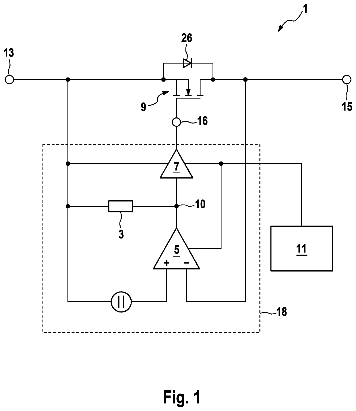
[0019]A polarity reversal protection arrangement that has a transistor circuit, an amplifier circuit and an output driver stage. In this case, the amplifier stage is connected to the output driver stage and the output driver stage is connected to the transistor circuit. The polarity reversal protection circuit furthermore has a first connection node and a second connection node that are connected to one another via the transistor circuit. The first connection node creates the connection to an on-board power system (what is called the KL30 terminal) and the second connection node creates the connection to one or more control devices (what is called the KL30B terminal). An electrical connection between the first connection node and the second connection node is able to be created or disconnected by way of the transistor circuit. The output driver stage is furthermore designed as a tri-state stage.

[0020]The amplifier circuit is designed to carry out the abovementioned linear mode. The ...


PUM


Abstract

A polarity reversal protection arrangement having a transistor circuit, an amplifier circuit and an output driver stage, wherein the amplifier circuit is connected to the output driver stage and the output driver stage is connected to the transistor circuit and the transistor circuit is arranged between a first connection node and a second connection node of the polarity reversal protection arrangement, such that an electrical connection between the first connection node and the second connection node is able to be created or disconnected by way of the transistor circuit, wherein the output driver stage is designed as a tri-state stage. A method for operating the polarity reversal protection arrangement and to a corresponding use.

Description

CROSS REFERENCE TO RELATED APPLICATIONS[0001]This application is a continuation application of PCT International Application No. PCT / EP2018 / 078868, filed Oct. 22, 2018, which claims priority to German Patent Application No. DE 10 2017 219 551.7, filed Nov. 3, 2017, wherein the contents of such applications are incorporated herein by reference.TECHNICAL FIELD[0002]A polarity reversal protection arrangement.TECHNICAL BACKGROUND[0003]Conventional control devices for motor vehicles in which a return flow of energy into the on-board power system is prevented in order not to jeopardize the safety of the vehicle. For this purpose, use is made of a transistor that does not allow the return flow at a node point to the on-board power system and protects the electronics of the control device against negative voltages (polarity reversal protection function).[0004]In what is known as the linear mode, the transistor (in particular FET) is driven such that it behaves like an ideal diode. When flow...

Claims


Application Information

Patent Timeline
Patent Type & Authority Applications(United States)
IPC IPC(8): H02H11/00H02H3/04H02H3/18G05F1/46B60R16/03
CPCH02H3/044G05F1/461H02H3/18H02H11/003B60R16/03
Inventor FAHLBUSCH, THORSTEN
Owner CONTINENTAL TEVES AG & CO OHG
Why Eureka
Try Eureka