Christmas light and straight-pin LED bead

a technology of led beads and lightemitting diodes, which is applied in the field of lighting, can solve the problems of poor homogeneity of color and brightness poor quality of straight-pin led beads so formed, and deviations (in respect of color and brightness). the effect of reducing resin loss and excellent homogeneity of straight-pin led beads

Inactive Publication Date: 2020-08-06
ZHOU XINGUO
View PDF0 Cites 0 Cited by
  • Summary
  • Abstract
  • Description
  • Claims
  • Application Information

AI Technical Summary

Benefits of technology

[0032]In the lighting fixture, the straight-pin LED bead, and the manufacturing process according to the present invention, the straight-pin LED bead uses sorted SMD LED(s) as a light source to provide excellent homogeneity of the straight-pin LED beads with reduced loss of resin and the first terminal pin and the second terminal pin during manufacturing. In the present invention, the SMD LED is directly connected to the first terminal pin and the second terminal pin and the first terminal pin and the second terminal pin provide an effect of enhancing heat dissipation so that the straight-pin LED bead so formed may have an extended lifespan and reduced light deterioration.

Problems solved by technology

Often, due to terminal pins of a straight-pin LED bead being slender, molding of the terminal pins requires high accuracy.
In automatic production, due to influence of progress of making the terminal pins, particularly the cup of 13a, the straight-pin LEDs so formed suffers poor homogeneity of color and brightness.
However, in the known techniques, it is inevitable that inferior quality products and deviations (in respect of color and brightness) may occur in the manufacturing process of the straight-pin LED bead.
The inferior quality products would lead to loss of the manufacturers in respect of resin used in a second encapsulation structure and first and second terminal pins.

Method used


Image

  • Christmas light and straight-pin LED bead
  • Christmas light and straight-pin LED bead
  • Christmas light and straight-pin LED bead

Examples


first embodiment

[0068]FIG. 8 is a schematic view showing a condition before the SMD LED and the first and second terminal pins are connected in a manufacturing process of the straight-pin LED bead according to the present invention. FIG. 9 is a schematic view showing a condition after the SMD LED and the first and second terminal pins shown in FIG. 6 are connected in the manufacturing process of the straight-pin LED bead. FIG. 10 is a schematic view showing a condition after the SMD LED shown in FIG. 9 is encapsulated with the second encapsulation structure in the manufacturing process of the straight-pin LED bead after the condition. FIG. 11 is a schematic view showing a condition after the first and second terminal pins shown in FIG. 10 are subjected to cutting in the manufacturing process of the straight-pin LED bead. Referring to FIGS. 8, 9, 10, 11, and 18, in the instant embodiment, the straight-pin LED bead manufacturing process comprises the following steps:

[0069]E, connecting first flat lea...

second embodiment

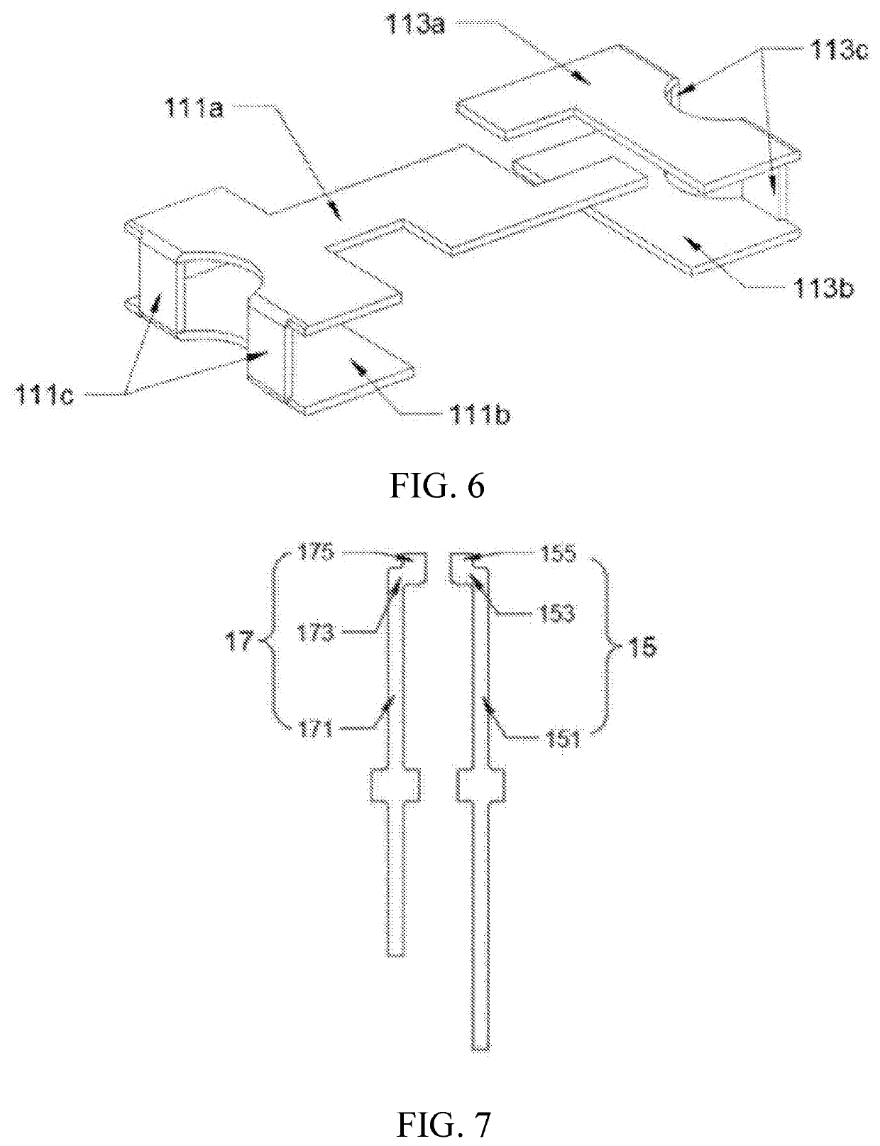
[0087]FIG. 15 is a schematic view showing a condition after SMD LEDs and first and second terminal pins are connected in a manufacturing process of a straight-pin LED bead according to the present invention. Referring to FIGS. 15 and 19, in the instant embodiment, two SMD LEDs are respectively arranged at two opposite sides of a first terminal pin and a second terminal pin, with first flat lead frames 111 being positioned flat on and attached to a side face of an upper end of the first terminal pin 15 and second flat lead frames 113 being positioned flat on and attached to a side face of an upper end of the second terminal pin 17.

third embodiment

[0088]FIG. 16 is a schematic view showing a condition after SMD LEDs and first and second terminal pins are connected in a manufacturing process of a straight-pin LED bead according to the present invention. Referring to FIGS. 16 and 20, in the instant embodiment, two SMD LEDs are respectively arranged at two opposite sides of a first terminal pin and a second terminal pin. A first flat lead frame 111 of one of the SMD LEDs is positioned flat on and attached to a side face of an upper end of the first terminal pin 15 and a second flat lead frame 113 is positioned flat on and attached to a side face of an upper end of the second terminal pin 17; and a first flat lead frame 111 of the other one of the SMD LEDs is positioned flat on and attached to a side face of the upper end of the second terminal pin 17 and a second flat lead frame 113 is positioned flat on and attached to a side face of the upper end of the first terminal pin 15.


PUM

PropertyMeasurementUnit
cross-sectional areasaaaaaaaaaa
cross-sectional aaaaaaaaaa
semiconductoraaaaaaaaaa

Abstract

A straight-pin LED bead includes an SMD LED, which includes an LED chip, a first flat lead frame, a second flat lead frame, and a first encapsulation structure that houses the LED chip and fixes the first and second flat lead frames. The LED bead further includes a first terminal pin electrically connected with the first flat lead frame, a second terminal pin electrically connected with the second flat lead frame, and a second encapsulation structure that houses the first encapsulation structure and fixes the first terminal pin, the second terminal pin. The straight-pin LED bead uses a sorted SMD LED as a light source so that the straight-pin LED bead so obtained has excellent homogeneity and the loss of resin and first and second terminal pins used are reduced. The SMD LED is directly connected to the first and terminal pins to enhance heat dissipation.

Description

(a) TECHNICAL FIELD OF THE INVENTION[0001]The present invention relates to the field of lighting, and more particularly to a lighting fixture, a straight-pin light-emitting diode (LED) bead, and a manufacturing method thereof.(b) DESCRIPTION OF THE PRIOR ART[0002]A light-emitting diode (abbreviated as LED) is a novel solid-state light source. Born in the 60s of the twentieth century, Lossen.o.w found light emission in an impurity P-N junction in 1923 in study of semiconductor SiC and developed light-emitting diode, which has been not paid attention to. With the quick progress of the electronic industry, the display technology got increasing attention of people in the 60s. The advantages of LEDs are long service life (>100,000 Hrs.), low driving voltage (1.8-4.5V), low power consumption (40-1000 mW), being a relatively cold light source (small radiation), high-speed lighting (time constant being 10-7 to 10-9 S), eliminating potential lighting effect, being small in size, multiple ...

Claims


Application Information

Patent Timeline
Patent Type & Authority Applications(United States)
IPC IPC(8): H01L33/62H01L33/56H01L33/50
CPCH01L2933/0066H01L33/507H01L33/647H01L2933/005H01L33/62H01L33/56H01L2933/0041H01L33/486H01L33/52
Inventor ZHOU, XINGUO
Owner ZHOU XINGUO
Why Eureka
Try Eureka