Electronic device and antenna structure thereof

a technology of electronic devices and antennas, applied in the direction of polarised antenna unit combinations, resonant antenna combinations, independent non-interacting antenna combinations, etc., can solve the problems of increasing the volume of terminal devices, affecting the quality of wireless communication, and difficult to meet the design requirements of product miniaturization, etc., to achieve good wireless transmission quality

Active Publication Date: 2020-07-23
PEGATRON
View PDF0 Cites 1 Cited by
  • Summary
  • Abstract
  • Description
  • Claims
  • Application Information

AI Technical Summary

Benefits of technology

The present invention provides an antenna structure and electronic device that can operate on multiple frequencies and have good wireless transmission quality. The antennas have different polarization directions, which increases isolation and reduces the number of antennas needed, saving manufacturing costs and meeting design requirements for product miniaturization.

Problems solved by technology

However, low isolation between the single-band antennas leads to mutual interference between the single-band antennas, affecting the quality of wireless communication.
An attempt to increase the isolation by increasing the distance between the sing-frequency antennas will inevitably increase the volume of the terminal device, making it difficult to meet the design requirements of product miniaturization.
However, the configuration of the frequency divider increases manufacturing costs and affects the wireless transmission quality because of filtering requirements.

Method used


Image

  • Electronic device and antenna structure thereof
  • Electronic device and antenna structure thereof
  • Electronic device and antenna structure thereof

Examples


Embodiment Construction

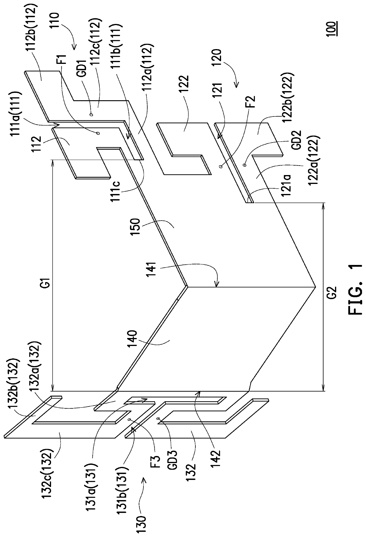
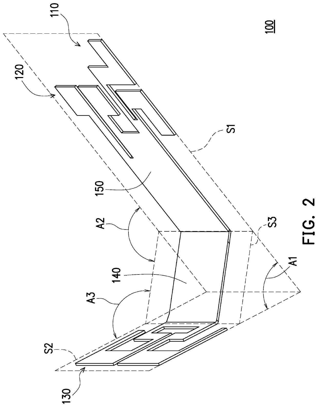
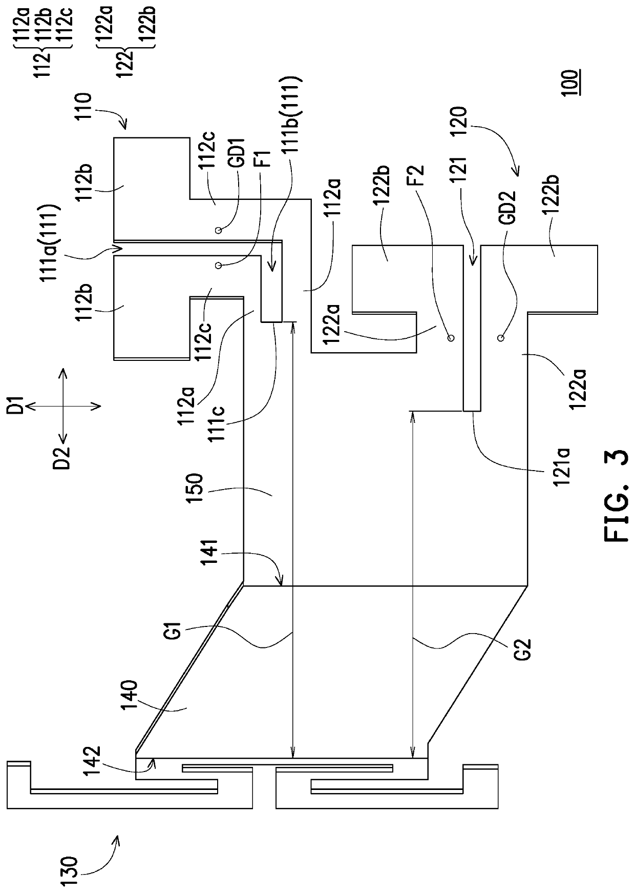
[0019]FIG. 1 is a schematic diagram of an antenna structure according to an embodiment of the present disclosure. FIG. 2 is a schematic diagram of the antenna structure of FIG. 1 from another viewing angle. Referring to FIG. 1 and FIG. 2, in this embodiment, the antenna structure 100 is a multi-band antenna structure, and can operate at two or more operating frequencies. One operating frequency may range from 2400 MHz to 2500 MHz and another operating frequency may range from 5150 MHz to 5850 MHz. The present disclosure is not limited thereto.

[0020]Further, the antenna structure 100 includes a first antenna 110, a second antenna 120, a third antenna 130, and a first grounding portion 140. The antenna structure 100 may be made by stamping and is an integrally formed metal sheet structure. The first grounding portion 140 includes a first side edge 141 and a second side edge 142 opposite to each other. The first antenna 110 and the second antenna 120 are connected to the first side edg...


PUM


Abstract

An antenna structure includes a first antenna, a second antenna, a third antenna, and a first grounding portion. The first antenna and the second antenna operate at a first frequency. The first antenna is disposed side by side with the second antenna, and the first antenna and the second antenna are orthogonally polarized. The third antenna operates at a second frequency, and the second frequency is lower than the first frequency. The first grounding portion includes a first side edge and a second side edge opposite to each other. The first antenna and the second antenna are connected to the first side edge and the third antenna is connected to the second side edge. An electronic device includes the said antenna structure.

Description

CROSS-REFERENCE TO RELATED APPLICATION[0001]This application claims the priority benefit of Taiwan application serial no. 108201011, filed on Jan. 21, 2019. The entirety of the above-mentioned patent application is hereby incorporated by reference herein and made a part of this specification.BACKGROUNDTechnical Field[0002]The present disclosure relates to an antenna structure and an electronic device, and in particular, to a multi-band antenna structure and an electronic device having the multi-band antenna structure.Related Art[0003]With the development of wireless communications technologies, an antenna configured to transmit and receive electric waves is an important component. Generally, to enable a terminal device support multiple frequencies, a commonly used method is to configure a plurality of single-band antennas in the terminal device. However, low isolation between the single-band antennas leads to mutual interference between the single-band antennas, affecting the qualit...

Claims


Application Information

Patent Timeline
Patent Type & Authority Applications(United States)
IPC IPC(8): H01Q21/30H01Q21/24
CPCH01Q21/24H01Q21/30H01Q1/2291H01Q9/285H01Q25/001H01Q5/20H01Q1/52H01Q25/00H01Q5/307H01Q1/241H01Q9/26H01Q21/28H01Q5/40H01Q21/293H01Q1/48H01Q1/243
Inventor YANG, HUI-ANHUANG, JUNG-YIHUANG, KUAN-CHUAN
Owner PEGATRON
Why Eureka
Try Eureka