
Imaging devices having piezoelectric transceivers

a piezoelectric transceiver and imaging device technology, applied in the direction of mechanical vibration separation, device material selection, instruments, etc., can solve the problem of degrading the electrical performance of the pmu

Active Publication Date: 2020-07-16
EXO IMAGING INC
View PDF0 Cites 8 Cited by
  • Summary
  • Abstract
  • Description
  • Claims
  • Application Information

AI Technical Summary

Benefits of technology

This design optimizes acoustic pressure performance while maintaining electrical performance by aligning electrode density with anti-nodal points, allowing for improved imaging and tissue analysis.

Problems solved by technology

However, as the size of the electrodes increases, the capacitance also increases to degrade the electrical performance of the pMUT.

Method used


Image

  • Imaging devices having piezoelectric transceivers
  • Imaging devices having piezoelectric transceivers
  • Imaging devices having piezoelectric transceivers

Examples


Embodiment Construction

[0032]In the following description, for purposes of explanation, specific details are set forth in order to provide an understanding of the disclosure. It will be apparent, however, to one skilled in the art that the disclosure can be practiced without these details. Furthermore, one skilled in the art will recognize that embodiments of the present disclosure, described below, may be implemented in a variety of ways, such as a process, an apparatus, a system, or a device.

[0033]Elements / components shown in diagrams are illustrative of exemplary embodiments of the disclosure and are meant to avoid obscuring the disclosure. Reference in the specification to “one embodiment,”“preferred embodiment,”“an embodiment,” or “embodiments” means that a particular feature, structure, characteristic, or function described in connection with the embodiment is included in at least one embodiment of the disclosure and may be in more than one embodiment. The appearances of the phrases “in one embodime...


PUM


Abstract

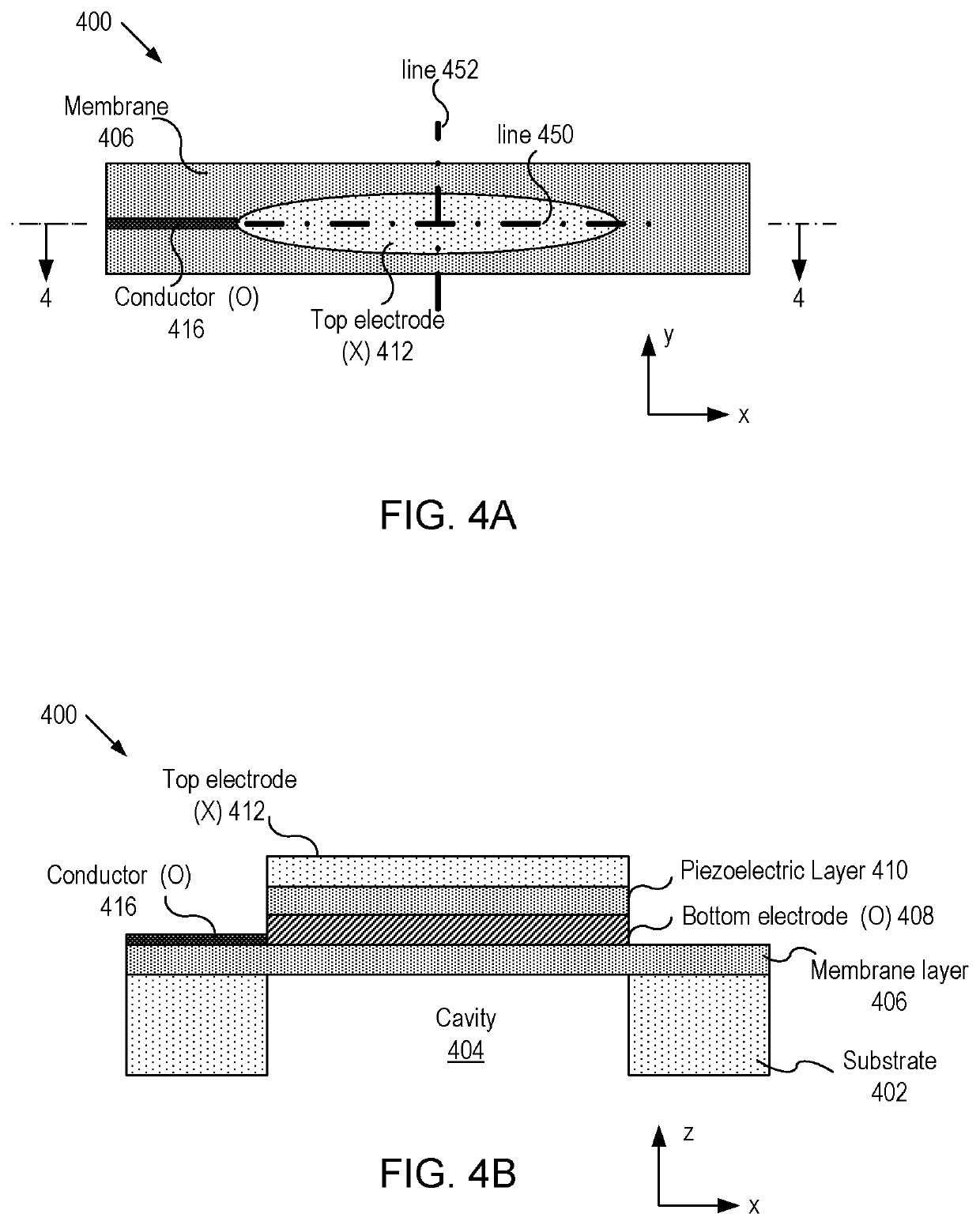
A micromachined ultrasonic transducer (MUT). The MUT includes: a substrate; a membrane suspending from the substrate; a bottom electrode disposed on the membrane; a piezoelectric layer disposed on the bottom electrode and an asymmetric top electrode is disposed on the piezoelectric layer. The areal density distribution of the asymmetric electrode along an axis has a plurality of local maxima, wherein locations of the plurality of local maxima coincide with locations where a plurality of anti-nodal points at a vibrational resonance frequency is located.

Description

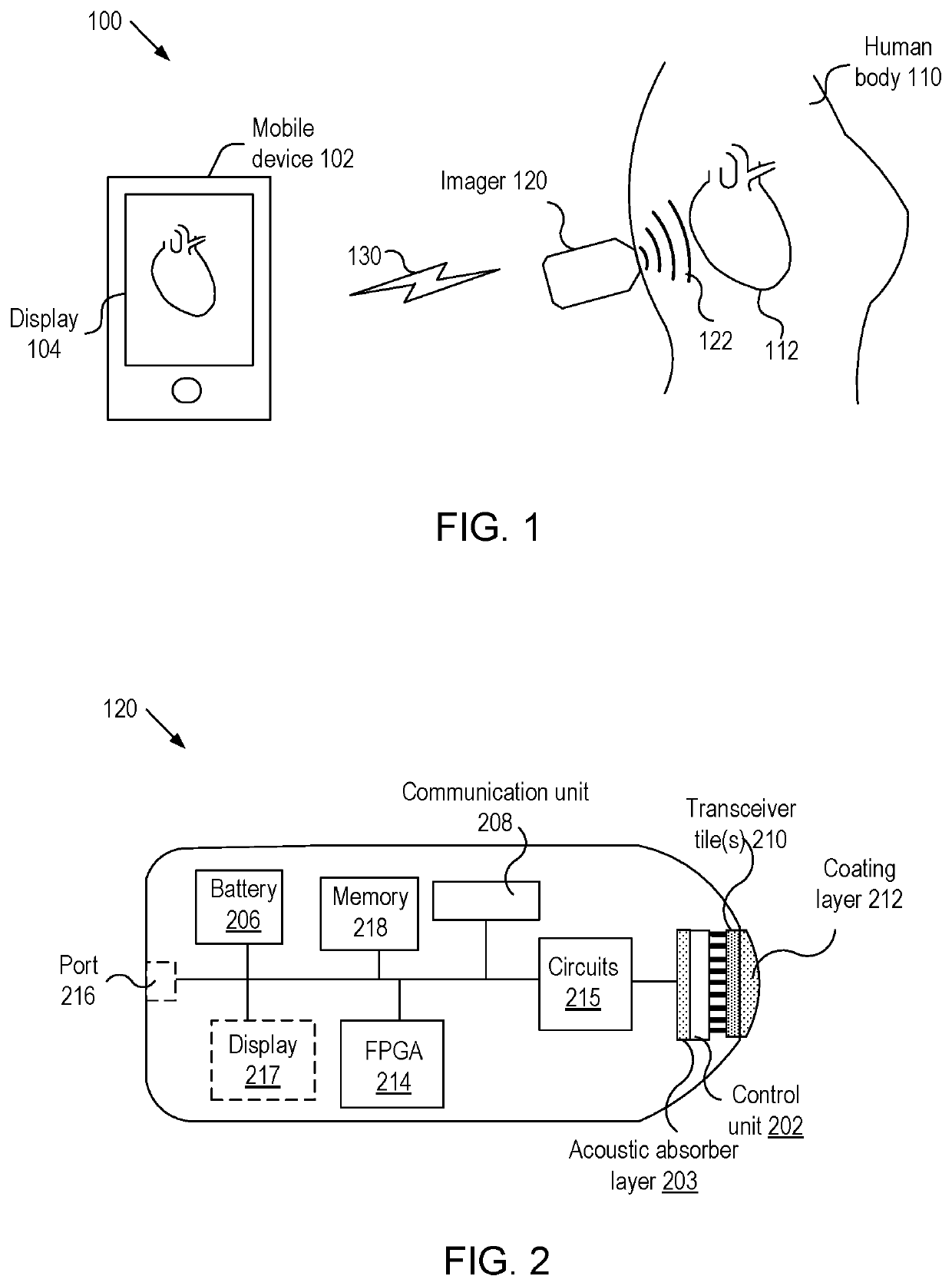
CROSS REFERENCE[0001]This application is a continuation of U.S. patent application Ser. No. 15 / 951,121, filed Apr. 11, 2018.BACKGROUNDTechnical Field[0002]The present invention relates to imaging devices, and more particularly, to imaging devices having micromachined ultrasound transducers (MUTs).Background of the Invention[0003]A non-intrusive imaging system for imaging internal organs of a human body and displaying images of the internal organs transmits signals into the human body and receives signals reflected from the organs. Typically, transducers, such as capacitive transduction (cMUTs) or piezoelectric transduction (pMUTs), that are used in an imaging system are referred to as transceivers and some of the transceivers are based on photo-acoustic or ultrasonic effects.[0004]In general, a MUT includes two or more electrodes and the topology of the electrodes affects both electrical and acoustic performances of the MUT. For instance, the amplitude of acoustic pressure generated...

Claims


Application Information

Patent Timeline
Patent Type & Authority Applications(United States)
IPC IPC(8): G01H11/08G01S15/02G01N29/07H01G5/00H01L41/113H01L41/18H10N30/20H10N30/30H10N30/85
CPCH01L41/1132G01S15/02G01H11/08H01G5/00B81B3/0021H01L41/183G01N29/07A61B8/00A61B8/0883A61B8/4488A61B8/4427A61B8/4494B06B1/0292B06B1/0688G01N29/2406G01S7/5208G01S15/8925G01S15/899G01N29/0654H10N30/2047H10N30/852H10N30/302
Inventor AKKARAJU, SANDEEPKWON, HAESUNGBIRCUMSHAW, BRIAN
Owner EXO IMAGING INC
Learn More