
Method and Apparatus for Torsional Magnetic Reconnection

Active Publication Date: 2020-07-09
SUNBEAM TECH LLC
View PDF0 Cites 3 Cited by
  • Summary
  • Abstract
  • Description
  • Claims
  • Application Information

AI Technical Summary

Benefits of technology

The invention provides a technology for conducting plasma physics experiments in a compact size, which reduces the cost and laboratory space needed. Additionally, the invention uses focused ion beam technology to ablate and etch material on a micrometer and nanometer scale. The size invariance of reconnection allows for wider beams to be formed, which further reduces milling time.

Problems solved by technology

Second, an externally driven instability is introduced that drives a bulk plasma flow, allowing current sheets to form in the vicinity of the null, thus forcing the break down of the frozen-in flux condition and allowing magnetic field line diffusion (slippages) through the plasma—the process of magnetic reconnection.
However, no narrow current sheets, no anomalous resistivity, and no plasma vortices on the scale of the electron inertial length were reported.
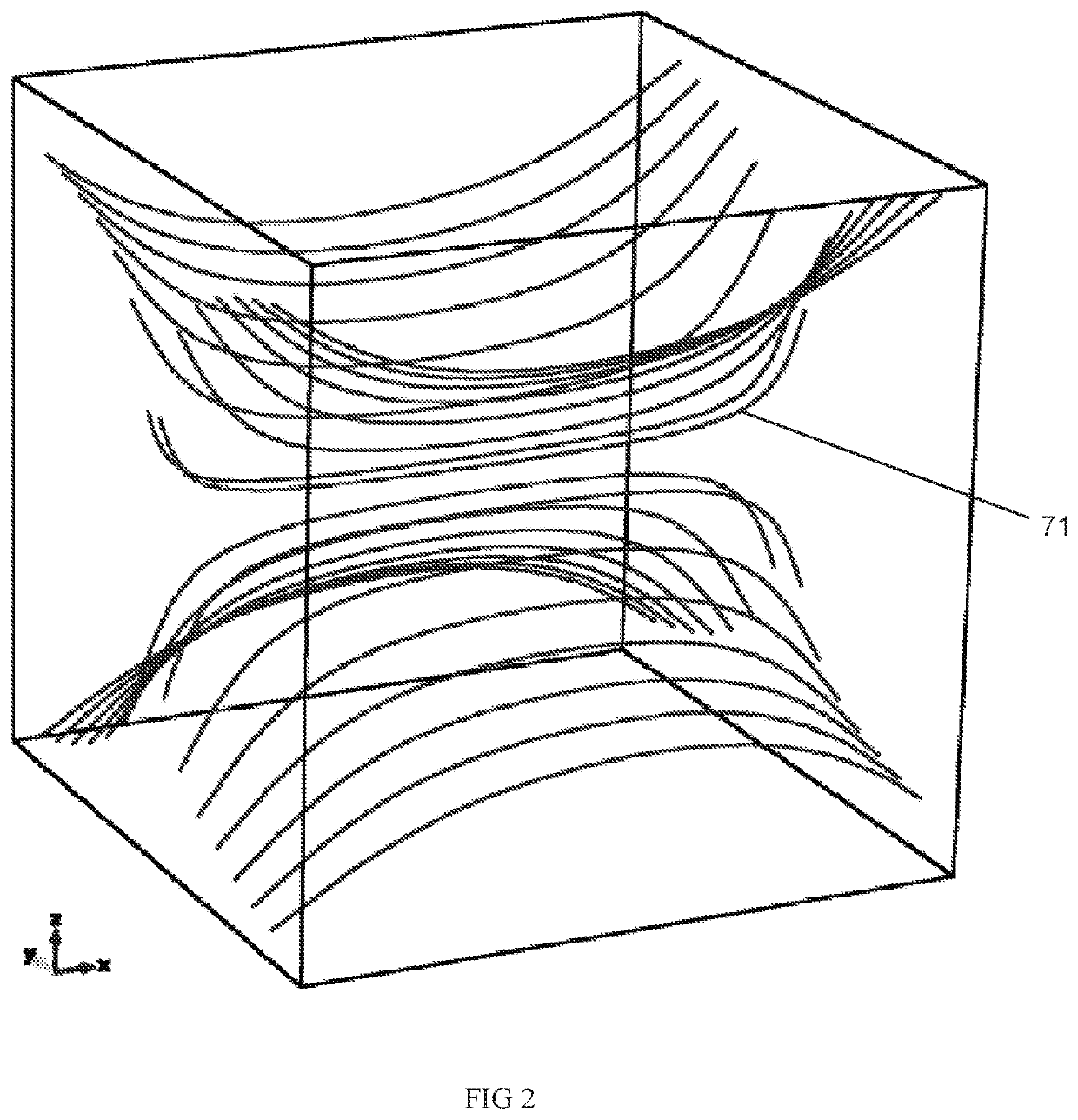
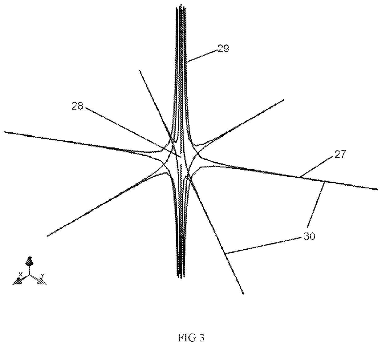
All of the previously reported laboratory magnetic reconnection configurations were met with a limited degree of success due to their inability to drive one of the three modes of three-dimensional reconnection about an isolated magnetic null point 28 of FIG. 3: torsional spine reconnection, torsional fan reconnection, or spine-fan reconnection.
These shortcomings render these various techniques as insufficient for fully describing the nature and origin of localized current sheet formation and current accumulation about isolated magnetic null points, as well as being insufficient for deciphering reconnection plasma heating and particle acceleration.
That is, there is no present apparatus capable of mimicking three-dimensional modes of magnetic reconnection, a scalable particle acceleration mechanism occurring across the wide range of length scales of astrophysical plasmas.

Method used


Image

  • Method and Apparatus for Torsional Magnetic Reconnection
  • Method and Apparatus for Torsional Magnetic Reconnection
  • Method and Apparatus for Torsional Magnetic Reconnection

Examples


embodiments

Embodiment 1

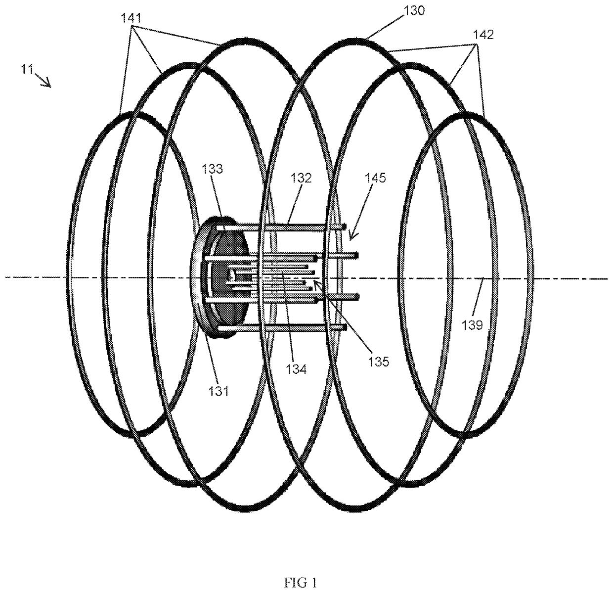
[0088]An apparatus for confining plasma and enabling torsional spine magnetic reconnection comprising:[0089]a vacuum environment housing;[0090]a conducting coil apparatus, comprising two hemispheres each adapted to carry oppositely flowing current, disposed within said vacuum environment housing and symmetrically displaced with respect to each other, further adapted to carry a plurality of electric currents for rapidly generating and maintaining a fan-spine magnetic field topology characterized by a spine axis normal to and intersecting a two-dimensional fan plane at a magnetic null, the two hemispheres having a longitudinal axis colinear with the spine axis, and a center co-located with the magnetic null;[0091]a plasma sheath apparatus having a plurality of outer electrodes connected to an outer electrode base, separated by an insulator from and surrounding a plurality of concentrically-arranged inner electrodes and a plasma surface, mounted within the vacuum environmen...

embodiment 2

[0092]An apparatus for confining plasma and enabling torsional spine magnetic reconnection comprising:[0093]a vacuum environment housing;[0094]a conducting coil apparatus, comprised of two hemispheres each adapted to carry oppositely flowing current, disposed within said vacuum environment housing and symmetrically displaced with respect to each other, further adapted to carry a plurality of electric currents for rapidly generating and maintaining a fan-spine magnetic field topology characterized by a spine axis normal to and intersecting a two-dimensional fan plane at a magnetic null, the two hemispheres having a longitudinal axis colinear with the spine axis, and a center co-located with the magnetic null;[0095]a dense plasma focus apparatus having a plurality of outer electrodes connected to an outer electrode base, separated by an insulator from and surrounding an inner electrode and a plasma surface, mounted within the vacuum environment housing parallel with the spine axis and...

embodiment 3

[0096]An apparatus for confining plasma and enabling torsional fan magnetic reconnection comprising:[0097]a vacuum environment housing;[0098]a conducting coil apparatus, comprised of two hemispheres each adapted to carry oppositely flowing current, disposed within said vacuum environment housing and symmetrically displaced with respect to each other, further adapted to carry a plurality of electric currents for rapidly generating and maintaining a fan-spine magnetic field topology characterized by a spine axis normal to and intersecting a two-dimensional fan plane at a magnetic null, the two hemispheres having a longitudinal axis colinear with the spine axis, and a center co-located with the magnetic null;[0099]a plurality of plasma sheath apparatuses each having a plurality of outer electrodes connected to an outer electrode base, separated by an insulator from and surrounding a plurality of inner electrodes arranged about a central axis on a plasma surface, mounted within the vacu...


PUM


Abstract

A method and apparatus for forming torsional magnetic reconnection, and converting stored magnetic energy into charged particle kinetic energy and particle acceleration, is claimed. A torsional magnetic reconnection apparatus generally comprises (1) a vacuum environment housing (2) a plurality of conducting coils to form a magnetic field fan-spine topology and (3) a plasma generation device providing an azimuthal magnetic field perturbation such that current sheets are formed and magnetic reconnection processes can occur. Electric current energization of the plurality of conducting coils generates a potential magnetic fan-spine topology. A simultaneous capacitor bank discharge forms and axially drives a plasma sheath, featuring an azimuthal magnetic field, toward the fan-spine magnetic null that forces the diffusion of magnetic flux through the plasma. This magnetic to plasma kinetic energy conversion process accelerates charged particles far away from the reconnection region along open magnetic field lines.

Description

CROSS REFERENCE TO RELATED APPLICATIONS[0001]This International Application claims benefit of priority under PCT Article 8 and 35 U.S.C. § 119(e) of U.S. Provisional Patent Application No. 62 / 664,968, filed May 1, 2018, entitled, “METHOD AND APPARATUS FOR TORSIONAL MAGNETIC RECONNECTION;” and U.S. Provisional Patent Application No. 62 / 696,909, filed Jul. 12, 2018, entitled, “METHOD AND APPARATUS FOR TORSIONAL MAGNETIC RECONNECTION.” Each of those provisional patent applications is incorporated herein by reference in its entirety.FIELD OF THE INVENTION[0002]The invention relates generally to the field of plasma physics, and, in particular, to methods and apparatuses for confining plasma to enable torsional magnetic reconnection, a process that converts stored magnetic energy into charged particle kinetic energy.BACKGROUND OF THE INVENTION[0003]In the art of laboratory plasma physics, investigations of magnetic reconnection are fundamental to the understanding of the storage and conve...

Claims


Application Information

Patent Timeline
IPC IPC(8): H05H1/16
CPCH05H1/16H05H1/24H05H1/10H01J37/32
Inventor CHESNY, DAVID LAWRENCEORANGE, NORTON BRICE
Owner SUNBEAM TECH LLC
Learn More