Method for in situ growth of axial geometry carbon structures in electrodes

a carbon structure and axial geometry technology, applied in the direction of electrode thermal treatment, cell components, electrical apparatus, etc., can solve the problems of reducing the coulombic charge capacity, cracking of the anode, and reducing the electrochemical cyclic performance, so as to improve the mechanical integrity and flexibility of the electrode 140, reduce the temperature of pyrolysis, and mitigate the effect of increasing the formation of a lithium-ion diffusion barrier

Active Publication Date: 2020-07-09
GM GLOBAL TECH OPERATIONS LLC
View PDF2 Cites 3 Cited by
  • Summary
  • Abstract
  • Description
  • Claims
  • Application Information

AI Technical Summary

Benefits of technology

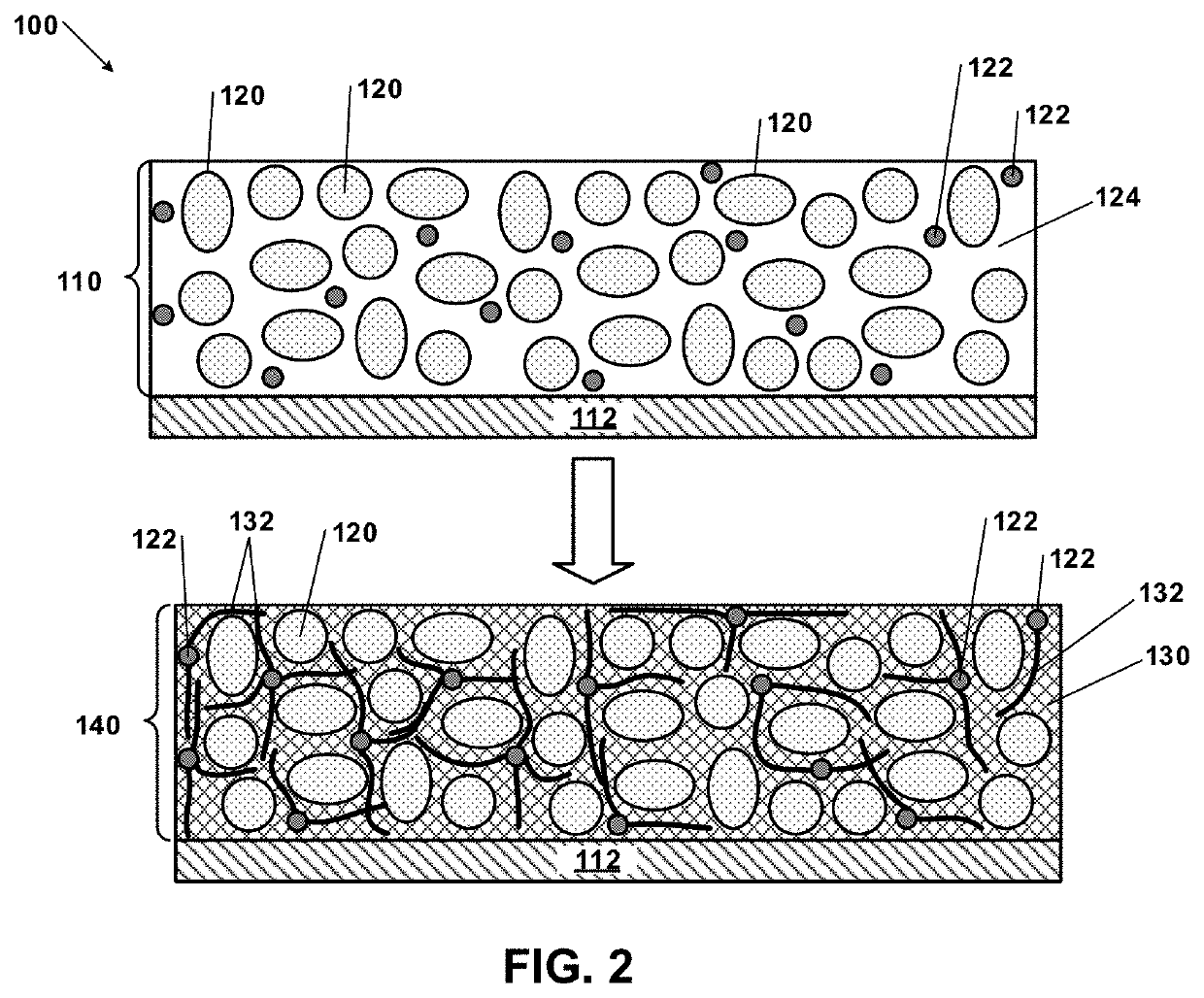
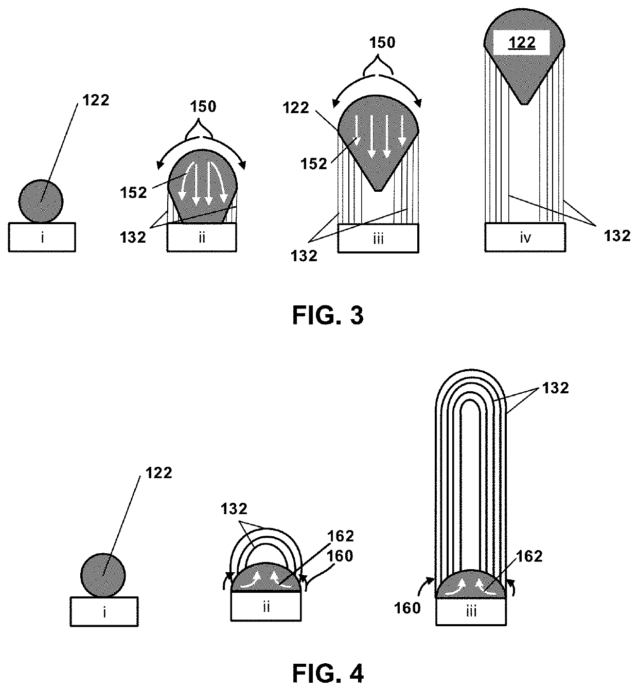
[0066]The slurry 110 may then be heated in an environment (e.g., having a temperature of less than about 1,000° C. as described below) to pyrolyze the polymer precursor 124 to form a carbonaceous conductive porous matrix 130. The carbonaceous conductive porous matrix 130 is electrically conductive. In this process, the plurality of catalytic nanoparticles 122 facilitates localized precipitation of carbon from the polymer precursor 124, so that the carbon grows and forms a plurality of axial geometry carbon structures 132. More specifically, the catalytic nanoparticles 122 can serve as nucleation sites to grow a plurality of axial geometry carbon structures 132, like carbon nanotubes or carbon nanofibers in situ, thus improving the mechanical integrity and flexibility of an electrode 140 formed.
[0067]In various aspects, the temperature during the heating / pyrolysis is less than or equal to about 1,000° C., optionally less than or equal to about 950° C., and in certain variations, optionally less than or equal to about 900° C. Such pyrolysis temperatures may be suitable where the catalytic nanoparticles comprise iron, cobalt, or alloys and combinations thereof. In certain aspects, for example, where the catalytic nanoparticles comprise iron, nickel, cobalt, and alloys and combinations thereof, the temperature during the heating / pyrolysis is less than or equal to about 895° C., optionally less than or equal to about 875° C., optionally less than or equal to about 850° C., optionally less than or equal to about 825° C., optionally less than or equal to about 800° C., optionally less than or equal to about 775° C., optionally less than or equal to about 750° C., optionally less than or equal to about 725° C., optionally less than or equal to about 700° C. In certain aspects, the temperature may be greater than or equal to about 500° C. to less than about 700° C. for the pyrolysis reaction. Due to the presence of the catalytic nanoparticles 122, the temperature for pyrolysis may be substantially reduced from other comparative methods. However, the temperatures used during the process are high enough to convert transitional metal ions into metallic nanoparticles when transition metal salts are used as precursors of the catalytic nanoparticles. Notably, the lower pyrolysis temperature can lead to less inactive material being formed, for example, where the electroactive material comprises silicon, less silicon carbide (SiC) is formed on the silicon active material surface and thus mitigating increased formation of a lithium-ion diffusion barrier at the Si—C interface.

Problems solved by technology

However, current anode materials comprising silicon suffer from significant drawbacks.
Silicon-containing electroactive materials experience large volume changes (e.g., volume expansion / contraction), for example, at about 300%, during lithium insertion / extraction (e.g., intercalation and deintercalation) that can result in cracking of the anode, a decline of electrochemical cyclic performance and diminished Coulombic charge capacity (capacity fade), and extremely limited cycle life.

Method used


Image

  • Method for in situ growth of axial geometry carbon structures in electrodes
  • Method for in situ growth of axial geometry carbon structures in electrodes
  • Method for in situ growth of axial geometry carbon structures in electrodes

Examples


Embodiment Construction

[0034]Example embodiments are provided so that this disclosure will be thorough, and will fully convey the scope to those who are skilled in the art. Numerous specific details are set forth such as examples of specific compositions, components, devices, and methods, to provide a thorough understanding of embodiments of the present disclosure. It will be apparent to those skilled in the art that specific details need not be employed, that example embodiments may be embodied in many different forms and that neither should be construed to limit the scope of the disclosure. In some example embodiments, well-known processes, well-known device structures, and well-known technologies are not described in detail.

[0035]The terminology used herein is for the purpose of describing particular example embodiments only and is not intended to be limiting. As used herein, the singular forms “a,”“an,” and “the” may be intended to include the plural forms as well, unless the context clearly indicates...


PUM

PropertyMeasurementUnit
temperatureaaaaaaaaaa

Abstract

Methods of forming a plurality of axial geometry carbon structures (e.g., carbon nanotubes or carbon fibers) in situ in an electrode of an electrochemical cell that cycles lithium ions are provided. Electroactive particles that undergo volumetric expansion are mixed with a polymer precursor and a plurality of catalytic nanoparticles comprising a metal selected from the group consisting of: iron, nickel, cobalt, alloys, and combinations thereof to form a substantially homogeneous slurry. The slurry is applied to a substrate and then heated in an environment having a temperature of ≤about 1000° C. and in certain aspects, ≤about 895° C. to pyrolyze the polymer precursor. The plurality of catalytic nanoparticles facilitates in situ precipitation of carbon to grow a plurality of axial geometry carbon structures. After the heating, the electrode includes an electrically conductive carbonaceous porous network comprising the plurality of electroactive particles and the plurality of axial geometry carbon structures.

Description

INTRODUCTION[0001]This section provides background information related to the present disclosure which is not necessarily prior art.[0002]High-energy density, electrochemical cells, such as lithium ion batteries can be used in a variety of consumer products and vehicles, such as Hybrid Electric Vehicles (HEVs) and Electric Vehicles (EVs). Typical lithium ion batteries comprise a first electrode (e.g., a positive electrode or cathode), a second electrode (e.g., a negative electrode or anode), an electrolyte material, and a separator. Cathode materials for lithium batteries typically comprise an electroactive material which can be intercalated with lithium ions, such as lithium-transition metal oxides or mixed oxides of the spinel type, for example including spinel LiMn2O4, LiCoO2, LiNiO2, LiMn1.5Ni0.5O4, LiNi(1-x-y)CoxMyO2 (where 0<x<1, y<1, and M may be Al, Mn, or the like), or lithium iron phosphates.[0003]The negative electrode typically includes a lithium insertion mater...

Claims


Application Information

Patent Timeline
Patent Type & Authority Applications(United States)
IPC IPC(8): H01M4/04H01M4/62H01M4/38H01M10/0525H01M4/134H01M4/1395
CPCH01M4/0471H01M4/0404H01M4/386H01M4/1395H01M10/0525H01M4/134H01M4/625H01M2004/021Y02E60/10
Inventor XIAO, XINGCHENGVERBRUGGE, MARK W.
Owner GM GLOBAL TECH OPERATIONS LLC
Why Eureka
Try Eureka