Carbon fiber complex material and manufacturing method thereof, manufacturing apparatus for carbon fiber complex material, prepreg, and carbon fiber reinforced plastic composite material
a manufacturing apparatus and carbon fiber technology, applied in the field of carbon fiber complex materials, can solve the problems of deterioration in mechanical properties, carbon nanotubes may not produce an anchoring effect on the matrix resin layer, and the risk of deterioration in adhesion at the interface between continuous carbon fibers, so as to achieve the effect of improving adhesion
- Summary
- Abstract
- Description
- Claims
- Application Information
AI Technical Summary
Benefits of technology
Problems solved by technology
Method used
Image
Examples
first embodiment
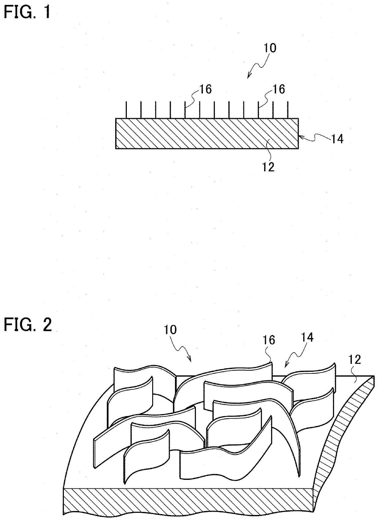
[0034]A first embodiment of this disclosure will be described below in detail with reference to the drawings. FIG. 1 is a diagram showing a configuration of a carbon fiber complex material 10. The carbon fiber complex material 10 is used in a carbon fiber reinforced plastic composite material. The carbon fiber complex material 10 may be used as a reinforcing material in the carbon fiber reinforced plastic composite material. The carbon fiber complex material 10 includes a carbon fiber material 14 formed from a continuous carbon fiber 12, and carbon nanowalls 16 formed on a surface of the continuous carbon fiber 12.
[0035]A carbon fiber material 14 is formed from a continuous carbon fiber 12. The continuous carbon fiber 12 may be made of a carbon fiber monofilament. The continuous carbon fiber 12 may be made of a carbon fiber bundle which is formed by bundling numerous carbon fiber monofilaments. For example, a 12K carbon fiber bundle formed by bundling 12000 carbon fiber monofilament...
second embodiment
[0068]Next, a second embodiment of this disclosure will be described below in detail with reference to the drawing. FIG. 8 is a flowchart showing a configuration of a method of manufacturing the carbon fiber complex material 10. The method of manufacturing a carbon fiber complex material of the second embodiment is different from the method of manufacturing the carbon fiber complex material 10 of the first embodiment mainly in that the method of the second embodiment includes a surface activation treatment step (S22). Note that the same constituents are denoted by the same reference signs and detailed explanations thereof will be omitted.
[0069]The method of manufacturing the carbon fiber complex material 10 includes a feeding step (S20), a surface activation treatment step (S22), a carbon nanowall forming step (S24) to be carried out subsequent to the surface activation treatment step (S22), and a winding step (S26). The manufacturing apparatus 20 for the carbon fiber complex materi...
third embodiment
[0082]Next, a third embodiment of this disclosure will be described in detail with reference to the drawing. The third embodiment involves a different configuration of the manufacturing apparatus for the carbon fiber complex material 10 from that of the second embodiment. FIG. 9 is a diagram showing a configuration of a manufacturing apparatus 100 for the carbon fiber complex material 10. FIG. 9 sets up the XYZ Cartesian coordinate system and positional relations among respective constituents will be described with reference to the XYZ Cartesian coordinate system. Moreover, a predetermined direction in a horizontal plane is defined as x-axis direction, a direction orthogonal to the x-axis direction within the horizontal plane is defined as a y-axis direction, and a direction (a vertical direction) orthogonal to the x-axis direction and to the y-axis direction is defined as z-axis direction. Note that the same constituents as above are denoted by the same reference signs and detailed...
PUM
| Property | Measurement | Unit |
|---|---|---|
| Temperature | aaaaa | aaaaa |
| Length | aaaaa | aaaaa |
| Height | aaaaa | aaaaa |
Abstract
Description
Claims
Application Information
 - R&D
- Intellectual Property
- Life Sciences
- Materials
- Tech Scout
- Unparalleled Data Quality
- Higher Quality Content
- 60% Fewer Hallucinations
Browse by: Latest US Patents, China's latest patents, Technical Efficacy Thesaurus, Application Domain, Technology Topic, Popular Technical Reports.
© 2025 PatSnap. All rights reserved.Legal|Privacy policy|Modern Slavery Act Transparency Statement|Sitemap|About US| Contact US: help@patsnap.com


