
Load operating device

Active Publication Date: 2020-06-25
HONDA MOTOR CO LTD
View PDF0 Cites 0 Cited by
  • Summary
  • Abstract
  • Description
  • Claims
  • Application Information

AI Technical Summary

Benefits of technology

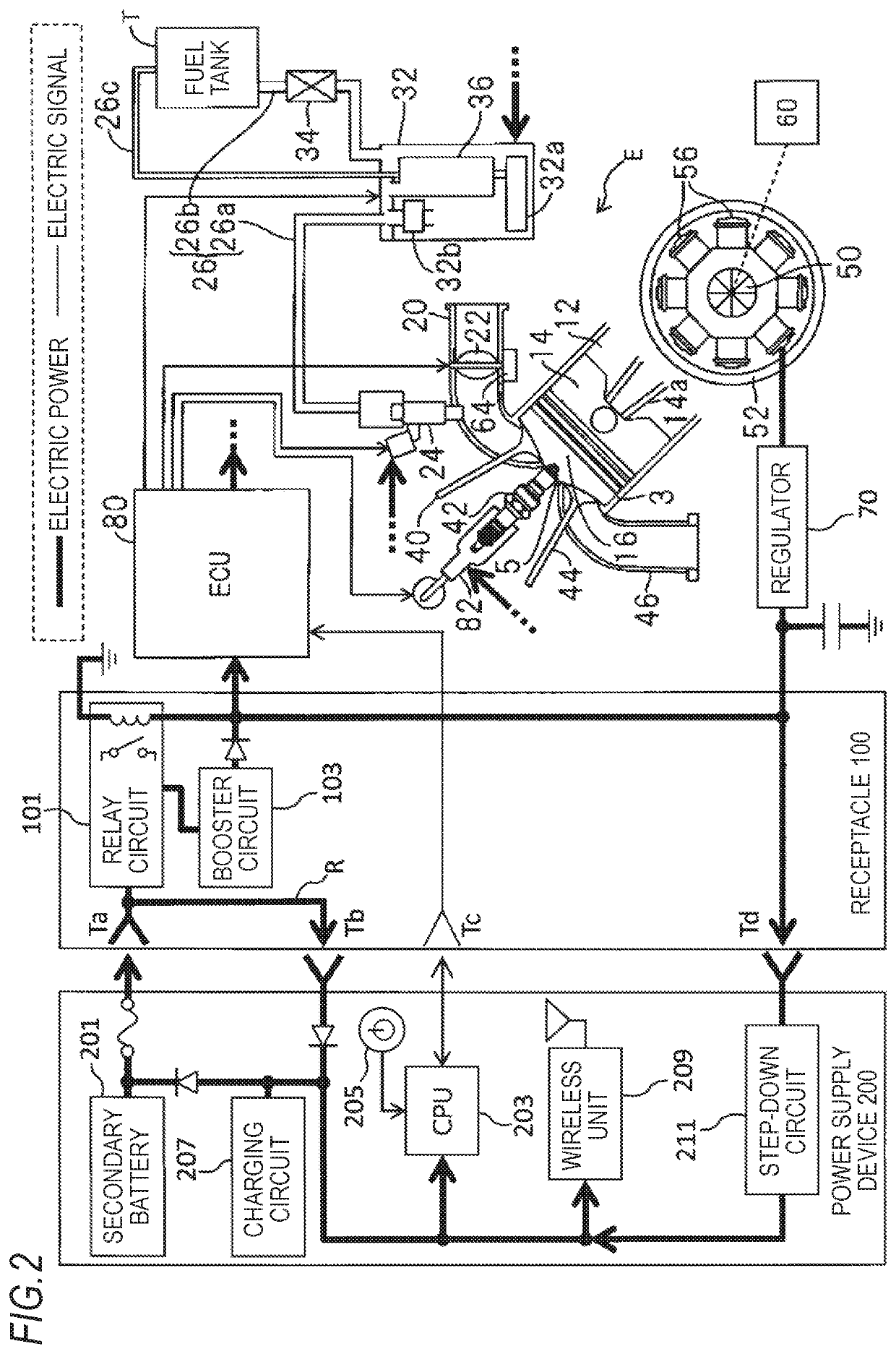
The patent describes a power supply device that can be connected to an electrical connection device and has a power supply circuit from a capacitor to a processing unit. When the power supply device is not attached to a load, the electrical path is not conductive, which prevents the charged amount of the capacitor from decreasing due to dark current. When the output voltage of the power generation unit exceeds the voltage applied to the load, a power supply path from the capacitor to the load is opened, stopping power supply to the load. This prevents the charged amount of the capacitor from decreasing. Additionally, when the load operates at a higher voltage than the output voltage of the capacitor, a booster circuit can be used to reduce the size of the power supply device.

Problems solved by technology

However, when the voltage of the dry battery is reduced, sufficient power for driving the fuel supply device cannot be obtained.

Method used


Image

  • Load operating device
  • Load operating device
  • Load operating device

Examples


Embodiment Construction

[0038]Hereinafter, an embodiment of the invention will be described with reference to the drawings. The drawings are viewed in the direction of the reference signs.

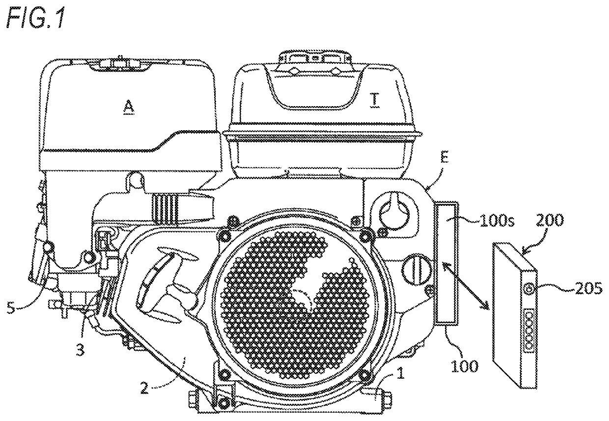
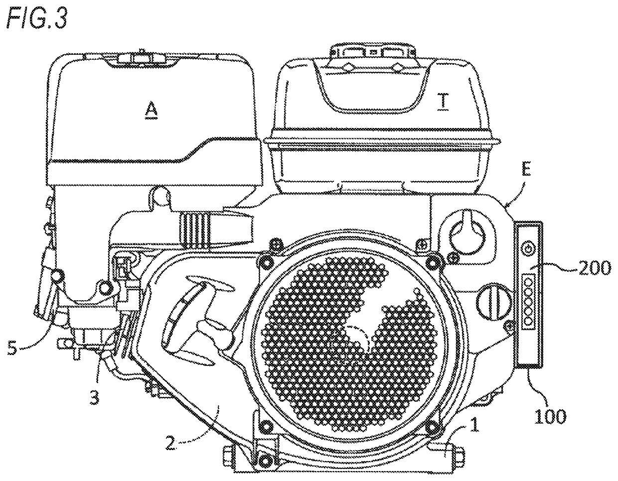
[0039]FIG. 1 is a diagram illustrating a relationship among a general-purpose engine, a receptacle, and a power supply device. As illustrated in FIG. 1, a power supply device 200 can be attached to and detached from a general-purpose engine E. The general-purpose engine E cannot be started up unless the power supply device 200 is attached to a receptacle 100 provided in the general-purpose engine E. The general-purpose engine E which can be operated by the power supply device 200 is associated with the power supply device 200 in advance. The general-purpose engine E is used as a power source for small industrial working machines for agriculture, construction, or the like.

[0040]As illustrated in FIG. 1, the general-purpose engine E includes a crankcase 2 having an installation flange 1 at the bottom, a cylinder block 3 ext...


PUM


Abstract

A load operating device includes a power supply device which is detachable from a load and can supply power to the load in a state of being attached to the load and an electrical connection device which is provided integrally with the load and electrically connects the power supply device and the load in a state where the power supply device is attached to the load. The power supply device has a capacitor which stores power to be supplied to the load and a processing unit in which a power supply circuit from the capacitor to the processing unit via the electrical connection device is established in a state where the power supply device is electrically connected to the electrical connection device.

Description

TECHNICAL FIELD[0001]The present invention relates to a load operating device including a power supply device which is detachable from a load and an electrical connection device which electrically connects the power supply device and the load and the power supply device.BACKGROUND ART[0002]Patent Literature 1 discloses an engine working machine in which a control circuit for driving a fuel supply device using a solenoid and a battery are efficiently mounted. The engine working machine requires a power supply for driving the fuel supply device and a dry battery is used to supply the power supply. A battery chamber for accommodating the dry battery is provided in a fan case and the dry battery can be easily accessed from the outside and is arranged at a position where it does not hinder the work.[0003]However, when the voltage of the dry battery is reduced, sufficient power for driving the fuel supply device cannot be obtained. Therefore, a form which uses a power supply which is deta...

Claims


Application Information

Patent Timeline
IPC IPC(8): F02D45/00H02J1/00H02J7/34
CPCF02D45/00H02J7/34H02J1/00F02D41/021F02D41/22F02D41/3082H02J2310/46H02J7/1446H02J7/345H02J2207/50H02J7/00
Inventor HASHIZUME, TAKASHIKANAYAMA, HISANORIFUJIMA, AKIFUMIBUNGO, KEIICHIRO
Owner HONDA MOTOR CO LTD
Learn More