
Hybrid vehicle and method for controlling hybrid vehicle

a hybrid vehicle and hybrid technology, applied in the direction of motor/generator/converter stopper, electric device, dynamo-electric converter control, etc., can solve the problems excessive lowering of the remaining capacity of the power storage device, and deteriorating fuel consumption, so as to improve fuel consumption and reduce the charging amount of the battery during regenerative braking. , the effect of deteriorating fuel consumption

Inactive Publication Date: 2015-03-12
TOYOTA JIDOSHA KK
View PDF0 Cites 13 Cited by
  • Summary
  • Abstract
  • Description
  • Claims
  • Application Information

AI Technical Summary

Benefits of technology

The technical effects of this patent text are to provide a hybrid vehicle and a method for controlling it that can prevent deterioration in fuel consumption caused by setting a low regeneration level. This allows for better fuel efficiency without sacrificing power output from the battery.

Problems solved by technology

Consequently, since the SOC of the battery is lowered, it would be necessary to start an engine, thereby deteriorating the fuel consumption on the contrary to the driver's intention.
Therefore, when the remaining capacity of the power storage device is excessively lowered due to a use of an auxiliary machine or the like, the internal combustion engine may be started.
Thus, the fuel consumption is deteriorated.

Method used

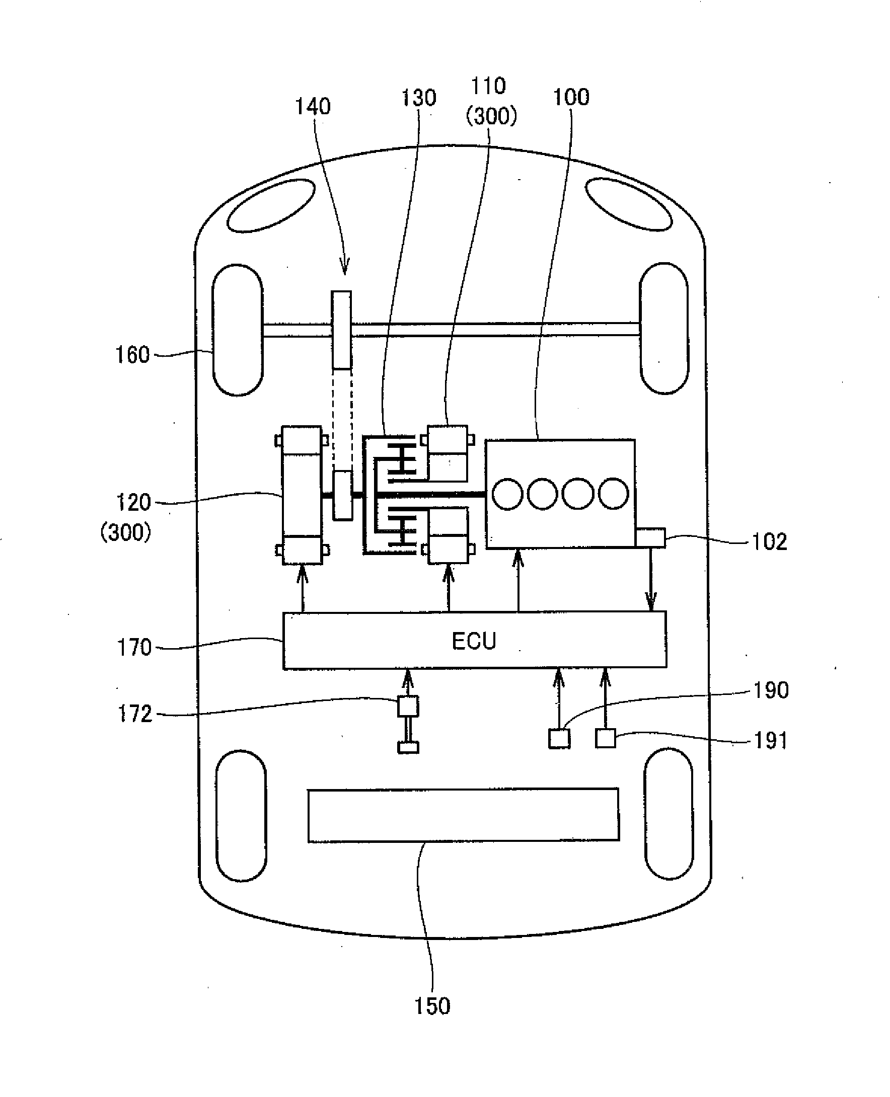
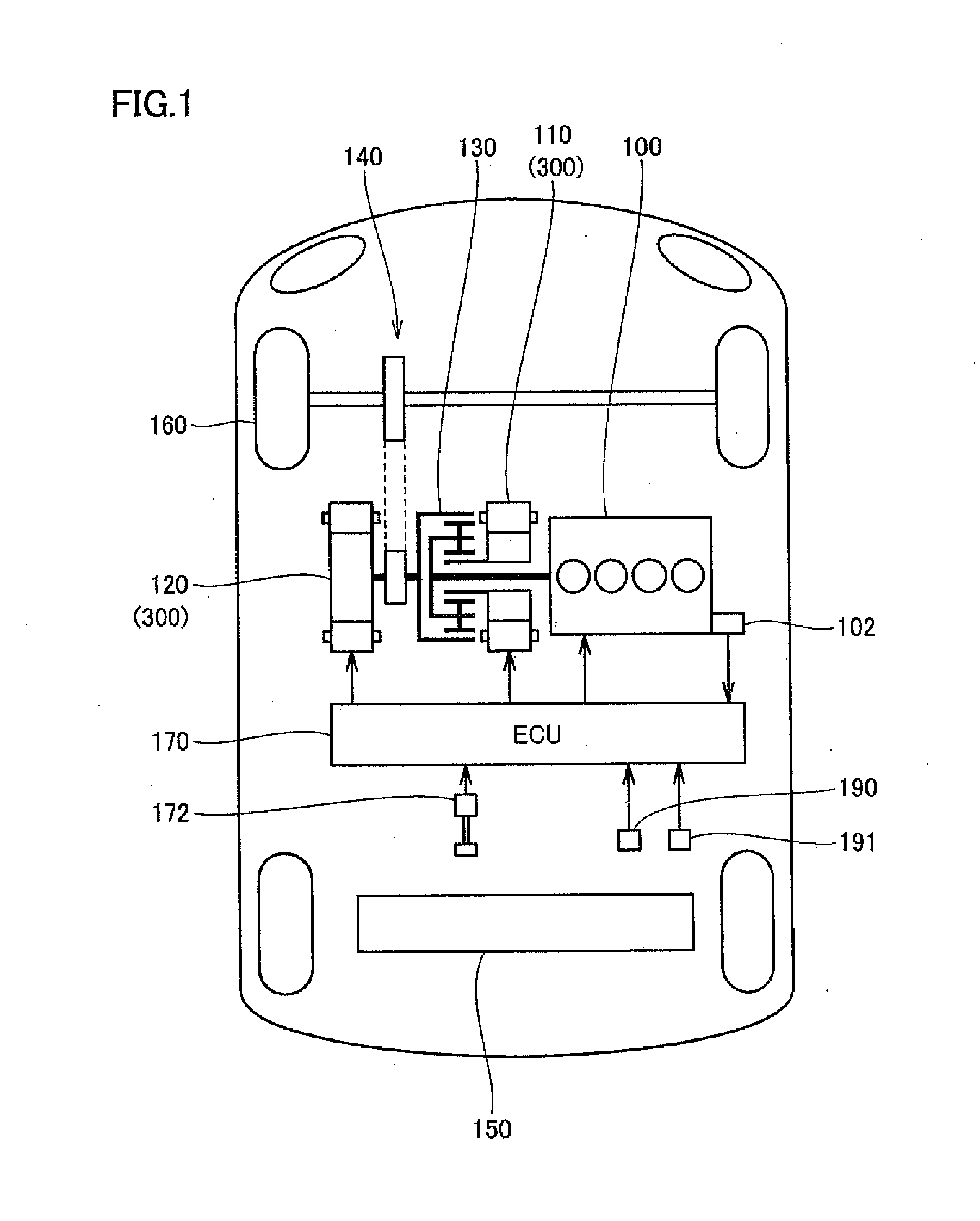
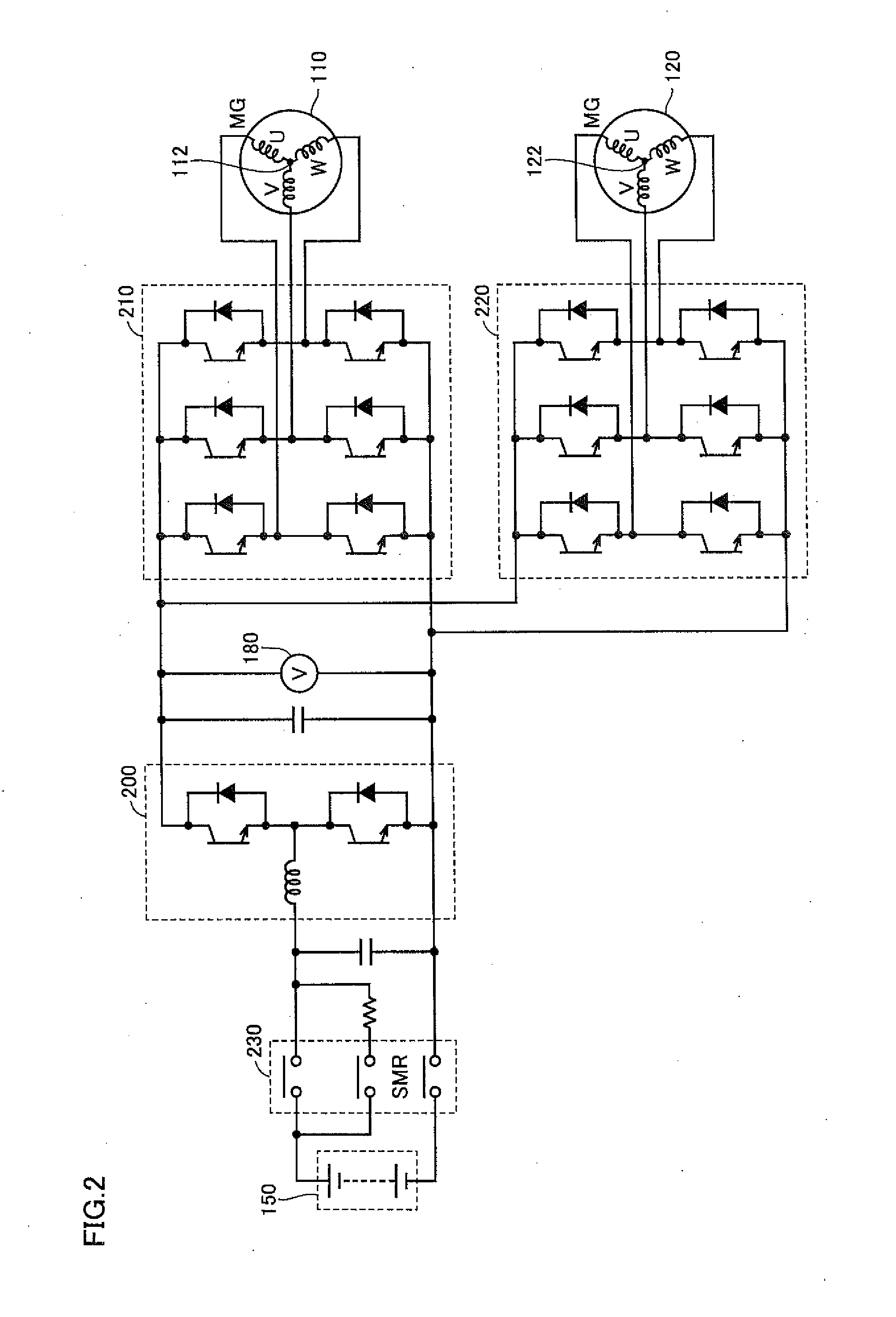

Image

  • Hybrid vehicle and method for controlling hybrid vehicle
  • Hybrid vehicle and method for controlling hybrid vehicle
  • Hybrid vehicle and method for controlling hybrid vehicle

Examples


modified example

[0104]The present invention is not limited to the embodiment described above.

[0105]Description will be made on the case where the regeneration level which can be selected by regeneration level selector 190 is limited to be smaller than the default regeneration level (the regeneration level in the D range).

[0106]FIG. 9 represents a relationship between the levels selected by regeneration level selector 190 and the regenerative braking force in the present modified example.

[0107]When regeneration level B0 or B1 is selected by regeneration level selector 190, the regenerative brake is operated respectively with regenerative braking force RB0 or RB1 during the off-state of the accelerator. When the D range (forward movement) is selected by select bar 191, and the regeneration level is not selected by regeneration level selector 190, the regeneration level is maintained at default level B2. At default level B2, the regenerative brake is operated with regenerative braking force RB2 during...

modified examples

[0110]The present invention is not limited to the embodiment described above, and also includes the following modified examples.

[0111](1) Series Type

[0112]The present invention can be also applied to a hybrid vehicle of a series type. Specifically, in the series type, the engine drives the first motor generator (power generator), and the generated electric power is stored in the battery. The second motor generator is driven by the electric power of the battery, so that a vehicle runs.

[0113]Also in this series-type hybrid vehicle, the ECU sets the power generation amount of the second motor generator to be larger by setting the regenerative braking force by the second motor generator during the off-state of the accelerator to be larger in the case where the regeneration level selected by the regeneration level selector is high than the case where the selected regeneration level is low. The ECU sets the charging amount from the first generator to the power storage during operation of ...


PUM


Abstract

An ECU sets a regenerative braking force generated by a second motor generator during an off-state of an accelerator to be larger in a case where a regeneration level is high than in a case where the selected regeneration level is low, thereby increasing a power generation amount of the second motor generator. The ECU sets a charging amount from first motor generator to battery during operation of an engine to be larger in a case where the regeneration level lower than the default level is selected by regeneration level selector than a case where the regeneration level is not selected by regeneration level selector.

Description

[0001]This nonprovisional application is based on Japanese Patent Application No. 2013-185023 filed on Sep. 6, 2013 with the Japan Patent Office, the entire contents of which are hereby incorporated by reference.BACKGROUND OF THE INVENTION[0002]1. Field of the Invention[0003]The present invention relates to a hybrid vehicle and a method for controlling a hybrid vehicle, and more particularly to a hybrid vehicle and a method for controlling a hybrid vehicle having a function of allowing a driver to select a regeneration level.[0004]2. Description of the Background Art[0005]Conventionally, there has been known a hybrid vehicle allowing a driver to select a braking level during regeneration.[0006]For example, according to a hybrid vehicle disclosed in Japanese Patent Laying-Open No. 2012-218697, during regenerative braking with use of a second motor generator, the second motor generator sets regeneration levels in stages in accordance with a user's operation to a paddle switch. Accordi...

Claims


Application Information

Patent Timeline
Patent Type & Authority Applications(United States)
IPC IPC(8): H02P3/14B60L50/16
CPCH02P3/14B60K6/28B60L7/18B60W10/06B60W10/18B60W10/26B60W20/00B60L7/14H02P3/18B60L1/003B60L1/02B60L3/0023B60L15/007B60L15/2009B60L2210/12B60L2210/14B60L2210/30B60L2210/40B60L2240/12B60L2240/14B60L2240/34B60L2240/421B60L2240/423B60L2240/427B60L2240/429B60L2240/441B60L2240/443B60L2240/445B60L2240/547B60L2240/549B60L2250/28B60L2260/26B60L15/2072B60L2260/24B60L2270/20B60K6/445B60W20/14B60W10/08B60W2510/244B60W2540/12B60W2710/0666B60W2710/083B60L50/61B60L50/16B60L58/13B60L50/66B60W2540/215Y02T10/62Y02T10/64Y02T10/70Y02T10/72Y02T10/7072
Inventor HISANO, TAISHI
Owner TOYOTA JIDOSHA KK
Learn More