Vehicular suspension
a technology of suspension and vehicle, applied in the field of suspension, can solve the problems of radio noise that can be generated, and achieve the effects of reducing the degree of freedom of molecules of rubber-like elastic components, reducing the charge amount of specific components, and reducing the charge amoun
- Summary
- Abstract
- Description
- Claims
- Application Information
AI Technical Summary
Benefits of technology
Problems solved by technology
Method used
Image
Examples
first embodiment
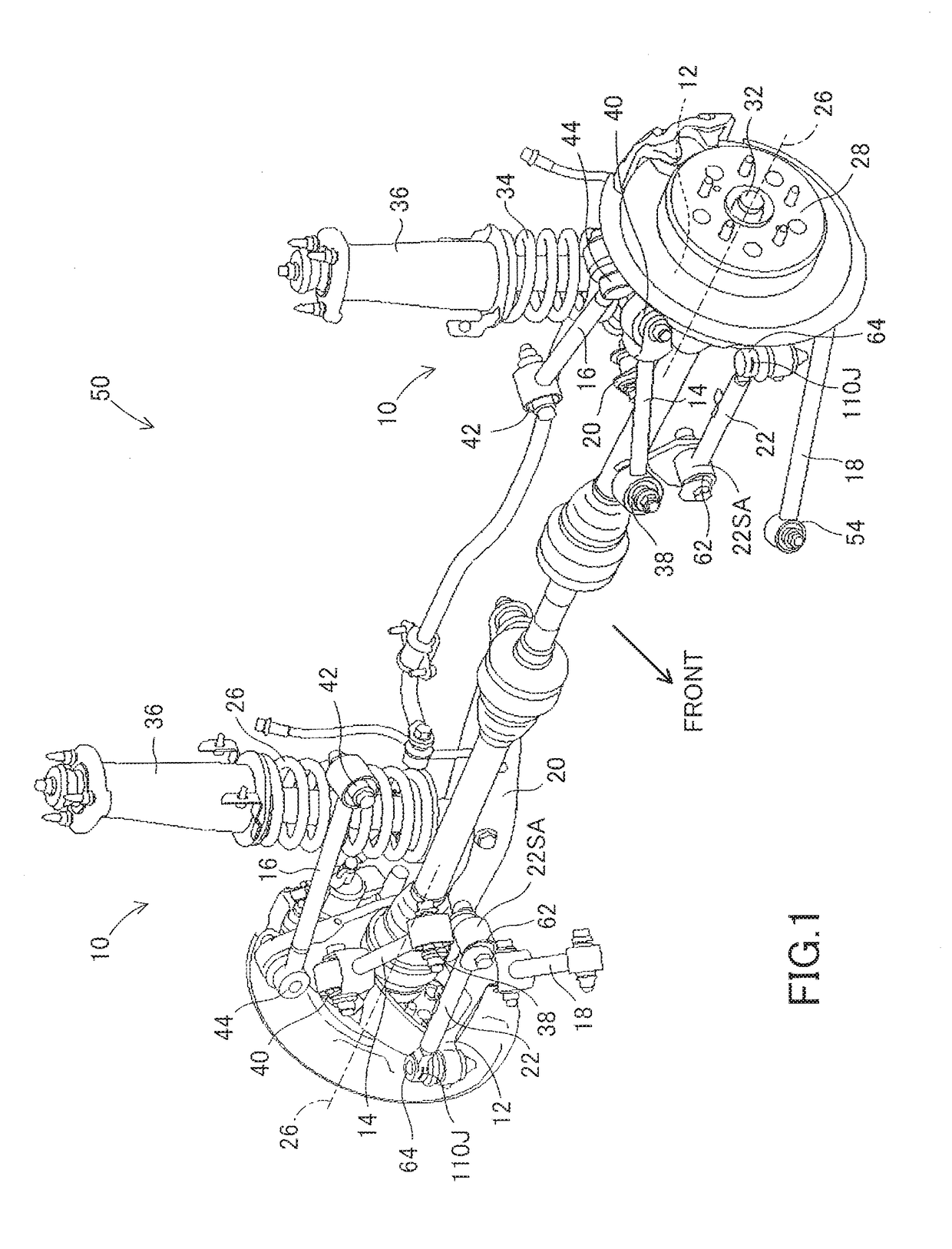
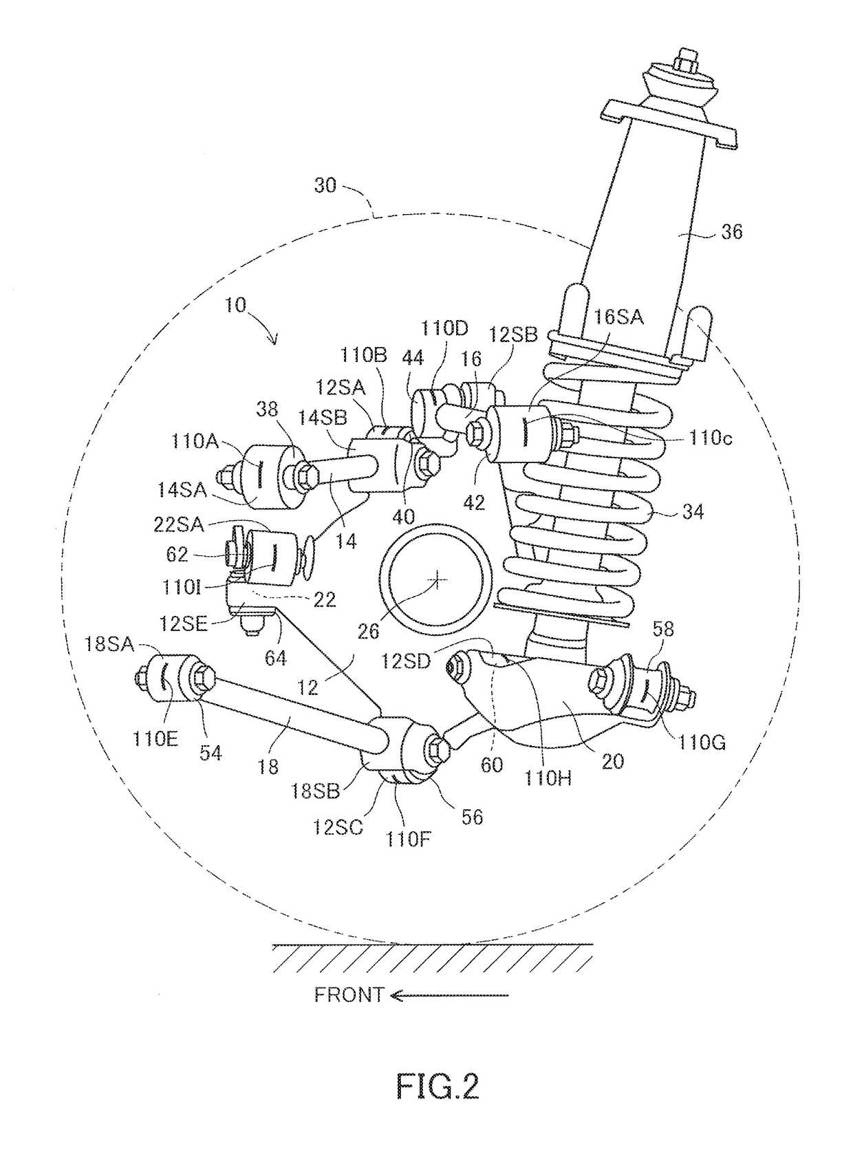
[0056]FIG. 1 to FIG. 10 are views for illustrating a suspension 10 according to a first embodiment of the present invention applied to a multi-link rear suspension and components thereof. In FIG. 1 to FIG. 3, “FRONT” indicates a front side of a vehicle 50. In each of FIG. 4 to FIG. 9 described later, a part of hatching indicating a cross section is omitted in order to avoid complexity.
[0057]In those drawings, the suspension 10 is provided for each of right and left wheels (rear wheels) 30 of the vehicle 50, and each suspension 10 includes a wheel support component (knuckle) 12 and five links 14 to 22. The links 14 to 22 are suspension components which are coupled to the wheel support component 12 and a suspension member 24 (see FIG. 3) forming a part of a vehicle body. The wheel support component 12 is configured to support an axle hub 28 so as to be rotatable about a rotation axis 26 through intermediation of a bearing (not shown). A wheel 30 (see FIG. 2) is mounted to the axle hub...
second embodiment
[0106]FIG. 13 is a perspective view for illustrating a suspension 120 according to a second embodiment of the present invention applied to a torsion beam rear suspension in a partially disassembled state, as viewed obliquely from the front of the vehicle. FIG. 14 is an enlarged horizontal sectional view for illustrating a bush device assembled to a trailing arm on a rear right wheel side illustrated in FIG. 13, which is taken along an axis thereof. FIG. 15 is a vertical sectional view for illustrating a cylinder part of the bush device illustrated in FIG. 13, which is taken along a direction perpendicular to an axis thereof.
[0107]The suspension 120 includes trailing arms 122L and 122R serving as left and right suspension components, which are separated from each other in the lateral direction of the vehicle 50 and extend in the front-and-rear direction of the vehicle, and a torsion beam 124 for integrally coupling those trailing arms to each other. As schematically illustrated in FI...
third embodiment
[0117]FIG. 16 and FIG. 17 are a plan view and a side view for illustrating a suspension 140 according to a third embodiment of the present invention applied to a four-link axle rear suspension.
[0118]In those drawings, the suspension 140 includes four control links 142L, 142R, 144L, and 144R, which are suspension components, and an axle housing 146 extending in the lateral direction of the vehicle 50. A housing 148H of a differential device 148 is integrally formed in a center part of the axle housing 146, but the housing 148H may be independent of the axle housing 146.
[0119]The axle housing 146 is configured to support an axle 152 coupled to the wheels (rear wheels) 150 at both ends so as to be rotatable about a rotation axis 154 through intermediation of bearings (not shown). Thus, the axle housing 146 and the bearings function as wheel support components. Although illustration is not made in FIG. 16 and FIG. 17, compression coil springs serving as suspension springs and shock abso...
PUM
 Abstract
Description
Claims
Application Information
 - R&D
- Intellectual Property
- Life Sciences
- Materials
- Tech Scout
- Unparalleled Data Quality
- Higher Quality Content
- 60% Fewer Hallucinations
Browse by: Latest US Patents, China's latest patents, Technical Efficacy Thesaurus, Application Domain, Technology Topic, Popular Technical Reports.
© 2025 PatSnap. All rights reserved.Legal|Privacy policy|Modern Slavery Act Transparency Statement|Sitemap|About US| Contact US: help@patsnap.com


