
Electric brake booster

a technology of brake booster and electric brake, which is applied in the direction of brake system, mechanical equipment, transportation and packaging, etc., can solve the problems of inability to perform active braking in a state, inconvenient operation of driver, and need to apply separate electronic or mechanical vacuum pumps, etc., to achieve reduced costs, simplified flow path configuration, and reduced probability of breakdown

Inactive Publication Date: 2020-06-04
HYUNDAI MOTOR CO LTD +1
View PDF0 Cites 0 Cited by
  • Summary
  • Abstract
  • Description
  • Claims
  • Application Information

AI Technical Summary

Benefits of technology

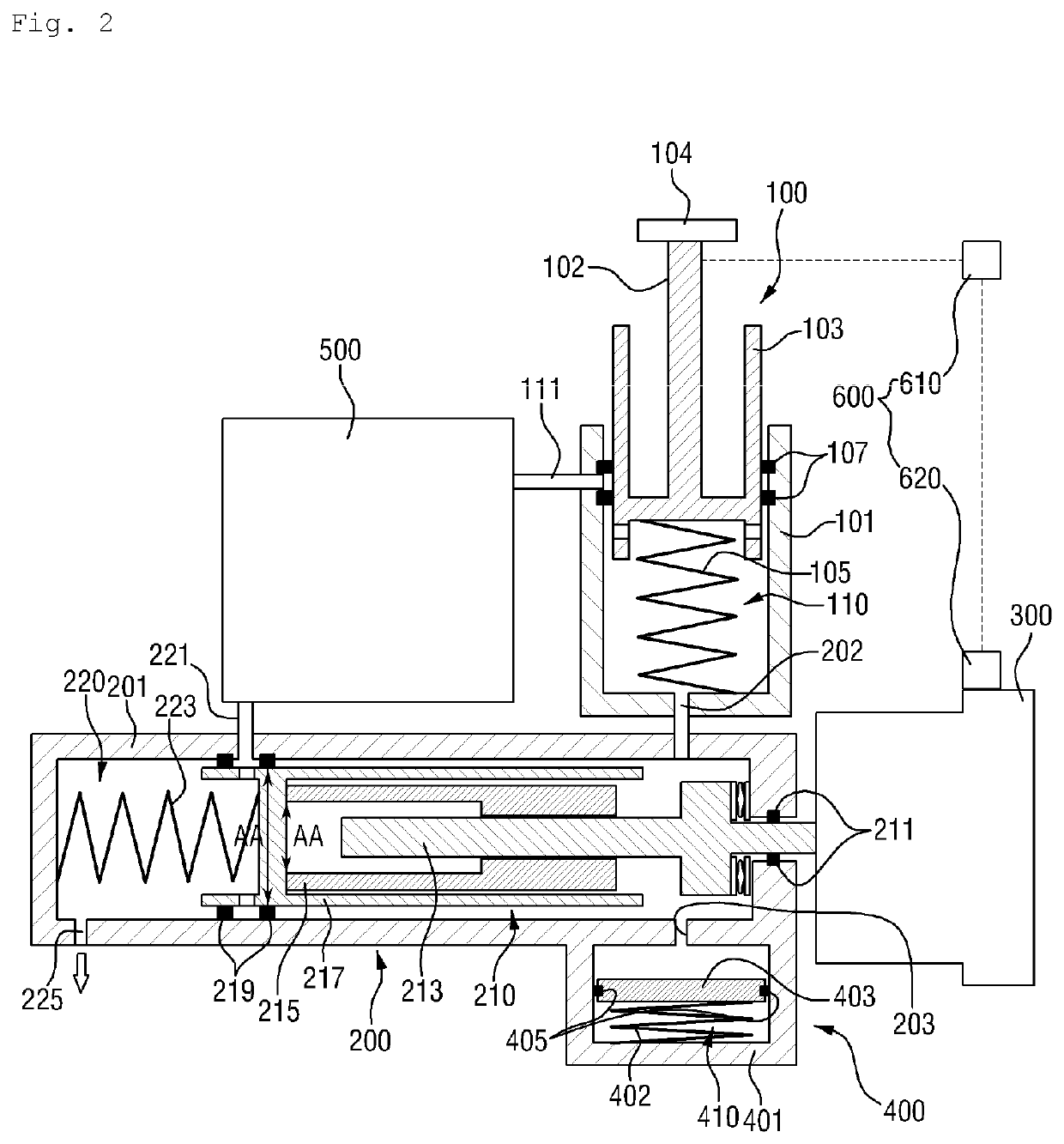
The present invention is an electric brake booster that simplifies the layout of the booster and improves braking performance when the motor is not operating or has limitations. The booster includes a first pressure device, a second pressure device, a sensing unit, and a buffer device. The second pressure device receives the brake fluid pressure from the first pressure device and the driving power of the motor. The sensing unit measures the displacement of the brake pedal and the rotation angle of the motor. The buffer device prevents an increase in pressure of the brake pedal when the motor does not operate. The rotation of the motor is controlled in accordance with the displacement of the brake pedal. The technical effects of this patent include improved braking performance and simplified layout of the booster.

Problems solved by technology

However, the vacuum brake booster in the related art has a problem in that a separate electronic or mechanical vacuum pump needs to be additionally applied in a case in which a vacuum in an engine is insufficient.
The vacuum brake booster in the related art has a problem in that it is impossible to perform active braking in a state in which a driver does not apply the brake.
However, the electro-hydraulic booster in the related art does not include a structure that buffers the reaction force being applied to a brake pedal of a driver when a motor breaks down or an operation of the motor is delayed.
As a result, there is a problem in that the driver is inconvenienced when braking the vehicle.
As a result, there are problems since the mounting position is limited, and it is difficult to ensure a gap at the periphery.

Method used


Image

  • Electric brake booster
  • Electric brake booster
  • Electric brake booster

Examples


Embodiment Construction

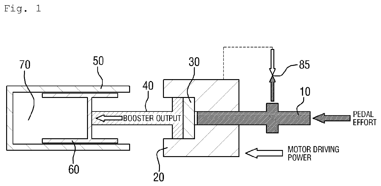
[0033]Hereinafter, the present disclosure is described in detail with reference to the accompanying drawings. However, the present disclosure is not restricted or limited by the embodiments. Like reference numerals indicated in the respective drawings refer to members, which perform substantially the same functions.

[0034]FIG. 1 is a view illustrating a state in which an electric booster in the related art operates.

[0035]Referring to FIG. 1, the electric booster in the related art includes a pedal rod 10 which transmits a pedal effort generated when a driver manipulates a brake pedal. The electric booster in the related art further includes a reaction disc 30, which is made of a rubber material and deformed depending on a state of force balance between a boosting body 20 and the pedal rod 10. The electric booster in the related art also includes a booster rod 40, which transmits an output of the booster to a piston 60. The electric booster in the related art further includes a chambe...


PUM


Abstract

An electric brake booster includes: a first pressure device, which generates brake fluid pressure via manipulation of a brake pedal; a second pressure device, which is connected to the first pressure device through a flow path at one side of the second pressure device, receives brake fluid pressure from the first pressure device, and receives driving power of a motor connected to another side of the second pressure device; a sensing unit mounted in the motor and measuring a displacement of the brake pedal and a rotation angle of the motor; and a buffer device connected to the second pressure device and preventing an increase in pressure of the brake pedal when the motor does not operate, in which motor rotation is controlled with a displacement of the brake pedal.

Description

CROSS-REFERENCE TO RELATED APPLICATIONS[0001]This application claims priority under 35 U.S.C. § 119 to Korean Patent Application No. 10-2018-0140267, filed on Nov. 14, 2018 in the Korean Intellectual Property Office, the disclosure of which is incorporated herein by reference in its entirety.BACKGROUND1. Field of the Disclosure[0002]The present disclosure relates to an electric brake booster for a vehicle, and particularly, to an electric brake booster which performs both a function of a modulator for applying different brake pressure to four wheels and a function of boosting a brake pedal effort generated as a driver manipulates a brake pedal. The electric brake booster also ensures redundancy of an actuator in order to prepare for autonomous driving of a vehicle.2. Description of the Related Art[0003]In general, most vehicles are mounted with power-assisted brake devices such as power brakes that allow a driver to decelerate or completely stop the vehicle even though the driver pr...

Claims


Application Information

Patent Timeline
Patent Type & Authority Applications(United States)
IPC IPC(8): B60T13/14B60T13/40B60T13/58B60T13/66
CPCB60T13/146B60T13/58B60T13/403B60T13/66B60T13/745B60T7/042B60T8/17B60T13/662B60T2220/04F16D65/18B60T13/72F16D2121/24F16D2125/10
Inventor LEE, JOUNG-HEECHA, GWAN-HYEONGJEON, GAB-BAEHWANG, SE-RA
Owner HYUNDAI MOTOR CO LTD
Learn More