
Vasectomy devices and methods for their use

Active Publication Date: 2020-06-04
SIGNATI MEDICAL INC
View PDF0 Cites 1 Cited by
  • Summary
  • Abstract
  • Description
  • Claims
  • Application Information

AI Technical Summary

Benefits of technology

The present invention describes a method for vasectomy that involves the use of new excising clamps or hooks and an improved bipolar coagulating device with arcuate jaws. The procedure involves securing the vas between the clamp or hook and the coagulating device, positioning the clamp or hook around the device, and using RF energy to thermally coagulate the tissue between the arcuate jaws. The duct and sheath are then debrided and divided using the same instruments. This method has advantages over other methods because it minimizes bleeding and swelling, avoids re-obstruction of the vas, reduces surgical steps and complications, and reduces the risk of transmission of blood-borne diseases.

Problems solved by technology

While the procedure appears simple, significant surgical skill is required, and complications may result.
Accordingly, even the slightest amount of persistent bleeding can cause a tremendously large hematoma.
In a similar manner, rough handling of the tissue can lead to significant swelling.
Even the most experienced vasectomy surgeon will occasionally encounter these problems.
Other disadvantages inherent in conventional surgical vasectomy, as exemplified by the NSV, include the prolonged surgical duration, which is generally on the order of twenty minutes or more.
In addition, conventional vasectomy procedures fail to adequately account for the natural tendency of the cut ends of the vas deferens to grow back together, thereby allowing the flow of sperm to the prostate and resumption of fertility.
Finally, because sharp instruments are used, performing a vasectomy on HIV+ patients presents a risk to the surgeon.
However, due to the inclusion of an integral excision element, the Pannell device tends to be complex, particularly if excision of the tissue is to be accomplished electrosurgically, as is the preferred embodiment.
Accordingly, it may be necessary for the clinician to exercise extreme care since displacement of the tissue may result in incomplete excision of the uncoagulated central tissue portion.
Given that tissue shrinks and forms a smooth lubricious surface when coagulated, such displacement may readily occur.

Method used


Image

  • Vasectomy devices and methods for their use
  • Vasectomy devices and methods for their use
  • Vasectomy devices and methods for their use

Examples


examples

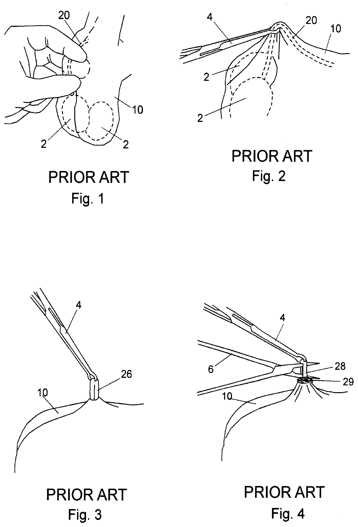
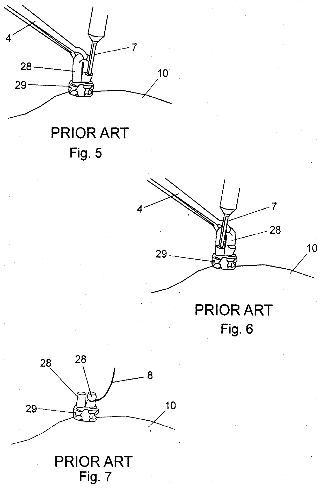
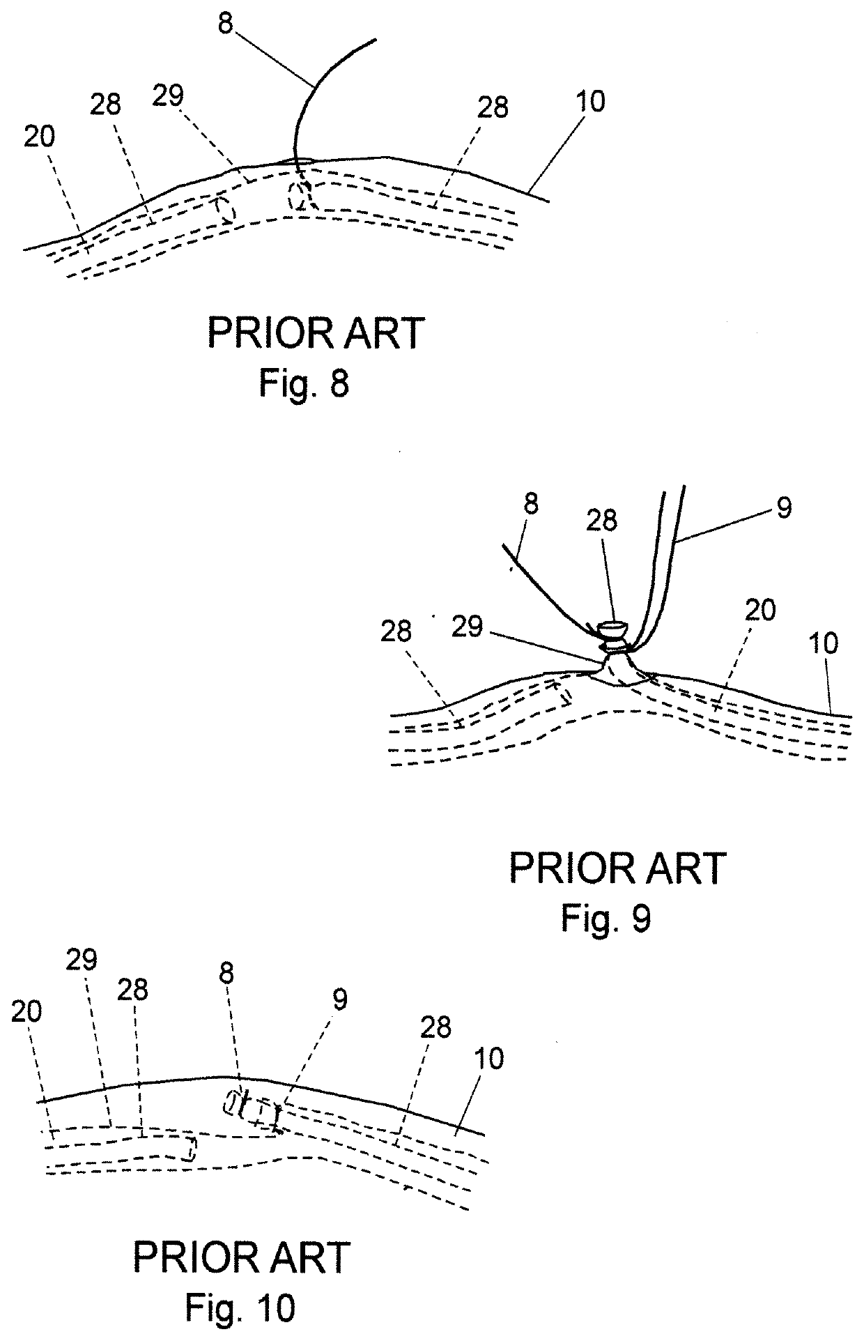
[0168]The most common method of vasectomy currently practiced is the no-scalpel vasectomy (NSV) in which the vas deferens is delivered from the scrotum via one or two openings formed by puncturing the scrotum and then expanding the opening(s). Steps of a standard prior-art NSV wherein a vas duct is occluded are depicted in FIGS. 1 through 10. In FIG. 1, a vas duct 20 is located in scrotum 10 using a standard three-finger technique. Thereafter, a local anesthetic is injected at the site. Duct 20 is then isolated in a fold of scrotum 10 using a ringed forceps 4 as shown in FIG. 2. The scrotum is then punctured using a dissecting forceps and the opening expanded sufficiently to allow the surgeon to deliver a portion 26 of vas duct 20 as depicted in FIG. 3. Dissecting forceps 6 are then used to puncture vas sheath 29 and then strip sheath 29 back to expose duct portion 28 as shown in FIG. 4. In FIGS. 5 and 6, duct portion 28 is hemi-dissected into abdominal and testicular portions, afte...


PUM


Abstract

Conventional vasectomy techniques suffer from a number of disadvantages, including, for example, a substantial risk for the development of hematomas and swelling, a potential for spontaneous regeneration and undesired resumption of fertility, a need for a highly skilled surgical professional, as well as a long recovery period, accompanied by severe limitations on post-surgical activity. The present invention overcomes the disadvantages and deficiencies of the prior art by providing a rapid, reliable, less invasive male sterilization procedure as well as vasectomy instruments and kits for use therewith.

Description

PRIORITY[0001]This application claims the benefit of U.S. Provisional Application Ser. No. 62 / 917,325 filed Dec. 3, 2018, the contents of which are hereby incorporated by reference in their entirety.TECHNICAL FIELD OF THE INVENTION[0002]The present invention relates to surgical instruments, and more particularly to surgical instruments and kits for performing vasectomies and methods for performing vasectomies using the instruments and kits.BACKGROUND OF THE INVENTION[0003]Vasectomy is surgical procedure that typically involves the removal of a portion of the ducts that carry sperm out of the testes (i.e., the vas deferens), thereby stopping the flow of sperm from the testicle to the prostate gland; once the vas deferens is interrupted, the sperm cannot be delivered and the man is rendered sterile. Currently used vasectomy methods, such as the No Scalpel Vasectomy (NSV), require that each vas deferens be dissected from the scrotum to allow the clinician to occlude and divide the vas ...

Claims


Application Information

Patent Timeline
IPC IPC(8): A61F6/20A61B17/3205A61B17/28
CPCA61F6/206A61B2017/2945A61B2018/00589A61B17/282A61B17/2816A61B17/3205A61F6/208A61B18/1442A61B2018/1422A61B2018/1452A61B2018/0063A61B17/12
Inventor VAN WYK, ROBERT A.
Owner SIGNATI MEDICAL INC
Learn More