
Circuit neuronal apte à mettre en oeuvre un apprentissage synaptique

a circuit neuronal and synaptic technology, applied in the field of circuit neuronal, can solve the problems of complex synaptic plane, significant variation in membrane voltage, and inability to realize synaptic learning synaptically, and achieve the effect of reducing the complexity of synaptic plane, densifying the structure of each one of the resistive memory synapses, and reducing the number of neurons

Inactive Publication Date: 2020-05-28
COMMISSARIAT A LENERGIE ATOMIQUE ET AUX ENERGIES ALTERNATIVES
View PDF5 Cites 9 Cited by
  • Summary
  • Abstract
  • Description
  • Claims
  • Application Information

AI Technical Summary

Benefits of technology

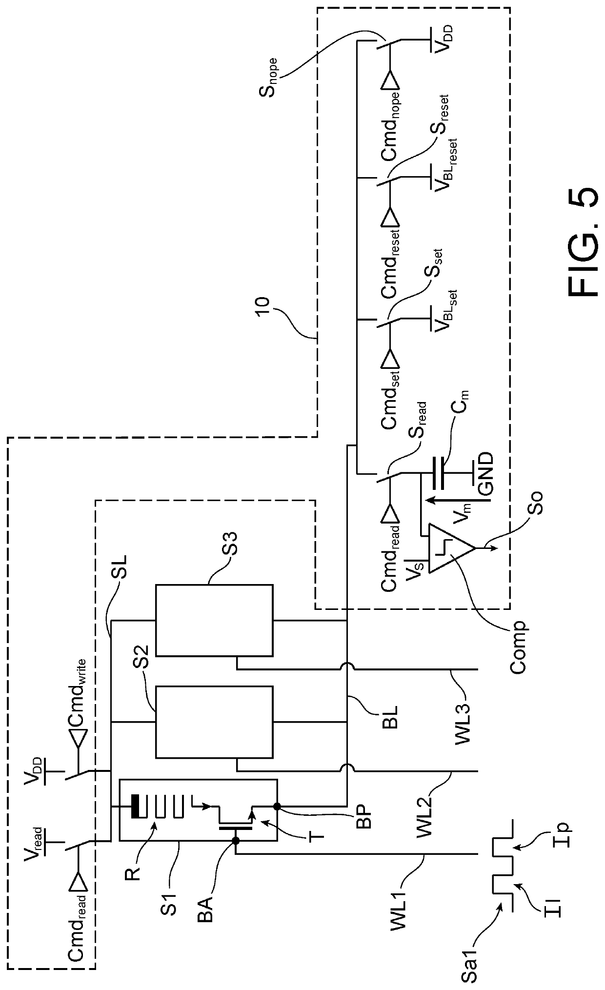
The invention proposes a simplified solution for learning the connections between neural layers using a synaptic integration circuit. This circuit includes a resistance memory synapse, an accumulator, a comparator, and a control unit. The control unit applies a conductance modification voltage to the synapse by controlling the application of apostsynaptic action signal. The circuit can be used for either potentiation or depression of the synapse, depending on the learning logic.

Problems solved by technology

The imbalance in charges between the inside and the outside of the cell induces a difference in voltage on either side of the membrane.
This results in a significant variation in the membrane voltage.
This instability results in the following behaviour.
This solution however requires densifying the structure of each one of the resistive memory synapses and complicates the synaptic plane by requiring that each postsynaptic neuron be connected to the synapses of a column not only by a Bit-Line connected to the propagation terminals of the synapses but also by an additional Bit-Line connected to a third access terminal of the synapses in addition to the activation and propagation terminals.

Method used


Image

  • Circuit neuronal apte à mettre en oeuvre un apprentissage synaptique
  • Circuit neuronal apte à mettre en oeuvre un apprentissage synaptique
  • Circuit neuronal apte à mettre en oeuvre un apprentissage synaptique

Examples


Embodiment Construction

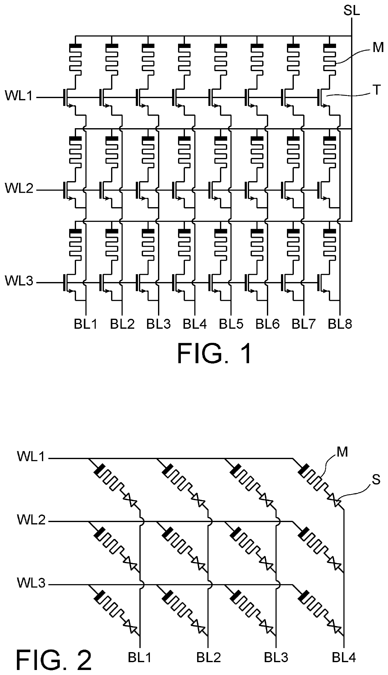
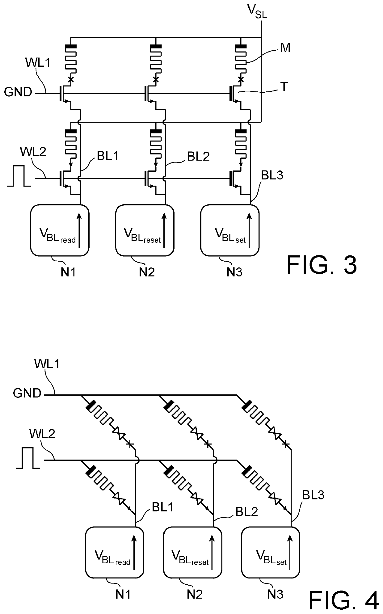
[0035]The invention has for framework a synaptic plane such as described hereinabove wherein the presynaptic spikes are injected one after the other on the corresponding Word-Line thereof. At each presynaptic spike of a neuron of the input layer, a complete line of synapses is activated and all of the neurons of the output layer are stimulated via the corresponding Bit-Line thereof according to the weight of the synapse that corresponds to them and which corresponds to the activated Word-Line.

[0036]During the learning, preferentially but not exclusively of the SDSP type, the weight of each synapse can be updated. With a learning of the SDSP type, such an update (i.e. a potentiation or a depression) is or is not produced according to solely the state of the postsynaptic neuron (its membrane voltage and its level of calcium).

[0037]Within the framework of the invention, the synapses are resistive memory synapses of the 1T1R or 1S1R type. In a possible implementation, the memories of th...


PUM


Abstract

A synaptic integration circuit for a neuromorphic chip comprising a resistive memory synapse which has an activation terminal to receive a presynaptic action signal and a propagation terminal intended to be connected to the circuit for transmitting a synaptic output signal which depends on the resistance of the memory. The circuit comprises an accumulator of the synaptic output signal, a comparator configured to emit a postsynaptic spike in case of the crossing of a threshold (Vm) by the accumulated output signal. It further comprises a control unit configured, when a presynaptic action signal is applied on the activation terminal, to impose a conductance modification voltage on the synapse by controlling the application of a postsynaptic action signal (VBL<sub2>set< / sub2>, VBL<sub2>reset< / sub2>) on the propagation terminal.

Description

TECHNICAL FIELD[0001]The field of the invention is that of neuromorphic chips with artificial neuron networks that make use of resistive memory synapses. The invention more particularly relates to the learning carried out directly on a chip of such a network of neurons.PRIOR ART[0002]A nerve cell, or neuron, can be broken down into several parts:[0003]The dendrites which are the inputs of the neuron via which it receives excitation or inhibition signals;[0004]The body of the neuron which is the theatre for ionic exchanges through the cell membrane;[0005]The axon, a long extension of the cell body, which is the sole output of the body.[0006]According to the excitation or inhibition signals received on the dendrites, ions transit through the cell membrane. The imbalance in charges between the inside and the outside of the cell induces a difference in voltage on either side of the membrane. This is then referred to as membrane voltage at the terminals of a membrane capacitance. When th...

Claims


Application Information

Patent Timeline
Patent Type & Authority Applications(United States)
IPC IPC(8): G06N3/063G06N3/08G11C13/00
CPCG11C13/0019G06N3/08G06N3/063G06N3/049G06N3/088G11C11/54G06N3/065
Inventor RUMMENS, FRANÇOISVALENTIAN, ALEXANDRE
Owner COMMISSARIAT A LENERGIE ATOMIQUE ET AUX ENERGIES ALTERNATIVES
Learn More