Electrode for resistance spot welding

a technology of electrodes and electrodes, applied in the direction of welding/cutting media/materials, welding apparatus, manufacturing tools, etc., can solve the problems of significant increase in the amount of energy needed to obtain significant increase in the amount of energy needed for resistance spot welding, and significant increase in the welding current value for obtaining the target nugget diameter. , to achieve the effect of efficient melting of metal plate materials, high current density and restraint of current paths

Active Publication Date: 2020-05-21
TOYOTA JIDOSHA KK
View PDF0 Cites 0 Cited by
  • Summary
  • Abstract
  • Description
  • Claims
  • Application Information

AI Technical Summary

Benefits of technology

The patent describes a configuration for an electrode used in resistance spot welding that reduces the amount of energy needed to achieve a target nugget diameter. The electrode tip has a projection portion and recess portions that destroy a film of oxidation on the metal plate materials being welded, prevent current concentration and excessive energy usage. The recess portions are independent of each other, which helps to restrain current paths from enlarging and ensures a higher current density. This results in more efficient melting of the metal plate materials and lower energy requirements for the weld. The electrode tip is designed to ensure even distribution of current and improved reliability in achieving the target nugget diameter.

Problems solved by technology

However, the configuration of this Japanese Patent Application Publication No. 2000-288744 (JP 2000-288744 A) causes a new problem in that the welding current value for obtaining the target nugget diameter (the amount of energy necessary for resistance spot welding) significantly increases as a result of the contact area that has become small.
That is, the configuration of this Japanese Patent Application Publication No. 2000-288744 (JP 2000-288744 A) can restrain the electrode tip portion from melting and adhering to each of the metal plate materials, but causes a significant increase in the amount of energy needed to obtain the target nugget diameter.
This significant increase in the necessary amount of energy is unfavorable because an electric power supply device is enlarged in size and environmental deterioration is caused.
This is because the film present on the surface of each of the metal plate materials cannot be sufficiently destroyed due to an insufficiency in the protrusion amount of the projection portion and the adhesion through melting may be caused when the depth of the recess portions is smaller than 30 μm.
Besides, this is because a working tool (a transfer plate) for molding the recess portions may be damaged (protrusions for molding the recess portions may be damaged in molding the recess portions) when the depth of the recess portions is greater than 150 μm.
This is because it is difficult to prepare the transfer plate when the distance between the central positions of those of the recess portions which are adjacent to each other is shorter than 400 μm.
Besides, this is because the film cannot be sufficiently destroyed due to too large a contact area between the electrode and each of the metal plate materials and the adhesion through melting may be caused when the distance between the central positions of those of the recess portions which are adjacent to each other is longer than 1200 μm.
This is because the transfer plate may be damaged (the protrusions for molding the recess portions may be damaged in molding the recess portions) when the length of one side of the opening end of each of the recess portions is shorter than 80 μm.

Method used


Image

  • Electrode for resistance spot welding
  • Electrode for resistance spot welding
  • Electrode for resistance spot welding

Examples


embodiment

Effect of Embodiment

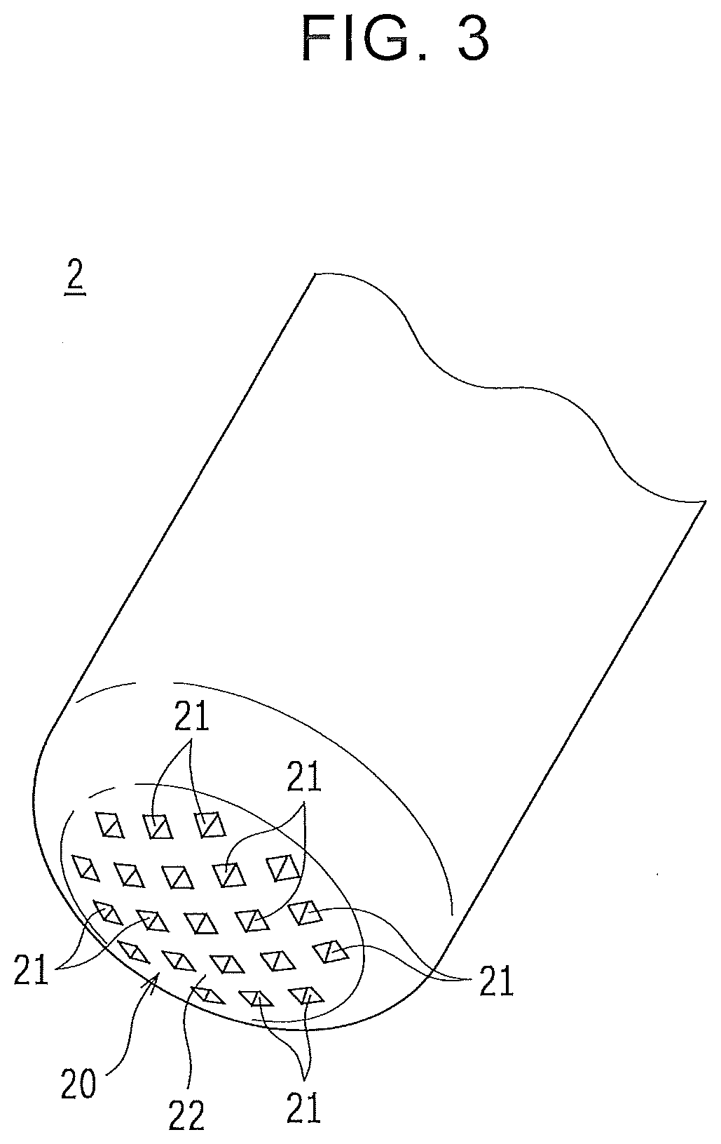
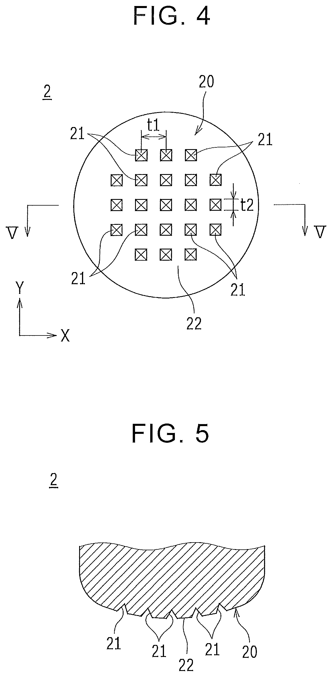
[0069]As described above, in the present embodiment, the electrode tip portion 20 is provided with the projection portion 22 and the recess portions 21, the plurality of the recess portions 21 are made independent of one another and dispersed at the electrode tip portion 20, and the projection portion 22 is the region other than the regions where the recess portions 21 are provided, and is configured to be equipped with the continuous surface that continues in the regions among the plurality of the recess portions 21 without being divided by the recess portions 21. Thus, the current paths can be restrained from being enlarged due to the fringing phenomenon at the projection portion 22, and a high current density can be ensured in each of the current paths. Therefore, the respective metal plate materials W1 and W2 can be joined to each other by efficiently melting the metal plate materials W1 and W2 while keeping the welding current value low, and the amount of en...

first experimental example

[0072]Next, a first experimental example conducted to confirm the foregoing effect will be described. This experimental example was conducted by measuring the amount of energy needed to obtain the target nugget diameter when the metal plate materials (the aluminum alloy plate materials) W1 and W2 were welded by the electrode according to the foregoing Japanese Patent Application Publication No. 2000-288744 (JP 2000-288744 A) and the electrodes 2 and 3 according to the present embodiment.

[0073]FIG. 8 is a perspective view of an upper electrode (which may be referred to hereinafter simply as an electrode) b according to Japanese Patent Application Publication No. 2000-288744 (JP 2000-288744 A) as viewed from below. As shown in this FIG. 8, the electrode b according to Japanese Patent Application Publication No. 2000-288744 (JP 2000-288744 A) has an electrode tip portion c where recesses d and projections e are provided in such a manner as to spread like concentric ripples. Besides, FI...

second experimental example

[0075]Next, a second experimental example will be described. This experimental example was conducted by measuring the relationship between the current value (the welding current value) and the nugget diameter when the metal plate materials (the aluminum alloy plate materials) were welded by each of an electrode having an electrode tip portion that is entirely a flat surface (hereinafter referred to as a first comparative example), the electrode according to the foregoing Japanese Patent Application Publication No. 2000-288744 (JP 2000-288744 A) (hereinafter referred to as a second comparative example), and the electrode according to the present embodiment.

[0076]FIG. 11 is a view showing an experimental result of the second experimental example. Each triangle in this FIG. 11 indicates the use of the electrode of the first comparative example, each square in this FIG. 11 indicates the use of the electrode of the second comparative example, and each circle in this FIG. 11 indicates the...


PUM

PropertyMeasurementUnit
Lengthaaaaaaaaaa
Lengthaaaaaaaaaa
Depthaaaaaaaaaa

Abstract

An electrode tip portion is provided with a projection portion and a plurality of recess portions. The plurality of the recess portions are independent of one another, and are provided at the electrode tip portion in a dispersed manner. The projection portion is a region other than regions where the recess portions are provided, and is configured to be equipped with a continuous surface that continues in regions among the plurality of the recess portions.

Description

INCORPORATION BY REFERENCE[0001]The disclosure of Japanese Patent Application No. 2018-215358 filed on Nov. 16, 2018 including the specification, drawings and abstract is incorporated herein by reference in its entirety.BACKGROUND1. Technical Field[0002]The disclosure relates to an electrode for resistance spot welding. In particular, the disclosure relates to an improvement in an electrode tip portion.2. Description of Related Art[0003]As an electrode used for resistance spot welding of metal plate materials (an electrode for resistance spot welding), there is known an electrode having an electrode tip portion (a surface of the electrode tip portion) where a projection portion and a recess portion are provided to destroy an oxidation film present on surfaces of the metal plate materials (especially aluminum alloy plate materials) (e.g., see Japanese Patent Application Publication No. 2000-288744 (JP 2000-288744 A)).[0004]The electrode disclosed in this Japanese Patent Application P...

Claims


Application Information

Patent Timeline
IPC IPC(8): B23K11/30B23K11/11
CPCB23K11/115B23K11/30B23K11/11B23K35/0205
Inventor HIOKI, TORUOOGA, MANABUYANAGAWA, TOMONORIKATO, SHUNGOTO, TAKASHIMATSUOKA, HIDEAKI
Owner TOYOTA JIDOSHA KK
Why Eureka
Try Eureka