Liquid double distribution device of use in particular in an apparatus in which a liquid phase flows under gravity

a distribution device and liquid phase technology, applied in the direction of liquefaction, lighting and heating apparatus, separation processes, etc., can solve the problems of unsatisfactory known double system with overflow and non-uniform distribution of stream

Active Publication Date: 2020-05-21
SAIPEM SPA
View PDF0 Cites 4 Cited by
  • Summary
  • Abstract
  • Description
  • Claims
  • Application Information

AI Technical Summary

Benefits of technology

[0016]A main object of the present invention is thus to provide a double liquid distribution device suitable for use in a fractionating or wash column, or in a coiled heat exchanger, or in any type of vertical apparatus that is the seat of a gravity flow of a liquid phase that needs to be distributed in uniform manner over a horizontal section of the apparatus in a zone under said liquid distribution device that overcomes the drawbacks of the double liquid distribution device with overflow, and in particular that guarantees uniform distribution of liquid over the entire section of a column, even while the column is being subjected to movements, and to do so over a range of flow rates that is sufficient, with flowrate distribution presenting uniformity in compliance with the expected criterion over the entire range of operating flow rates, which does not apply to existing systems with overflow while they are in the transition zone.

Problems solved by technology

The problem specific to these gravity flow vertical apparatuses installed on FPSOs or on FLNGs that are subjected to movements is that the acceleration vector to which the stream of liquid is subjected is no longer co-linear with the axis of the column, thereby giving rise to nonuniformities in the distribution of the stream over the section of the gravity flow apparatus.
Nevertheless, that known double system with overflow is not satisfactory, as explained below with reference to FIG. 5A.

Method used


Image

  • Liquid double distribution device of use in particular in an apparatus in which a liquid phase flows under gravity
  • Liquid double distribution device of use in particular in an apparatus in which a liquid phase flows under gravity
  • Liquid double distribution device of use in particular in an apparatus in which a liquid phase flows under gravity

Examples


Embodiment Construction

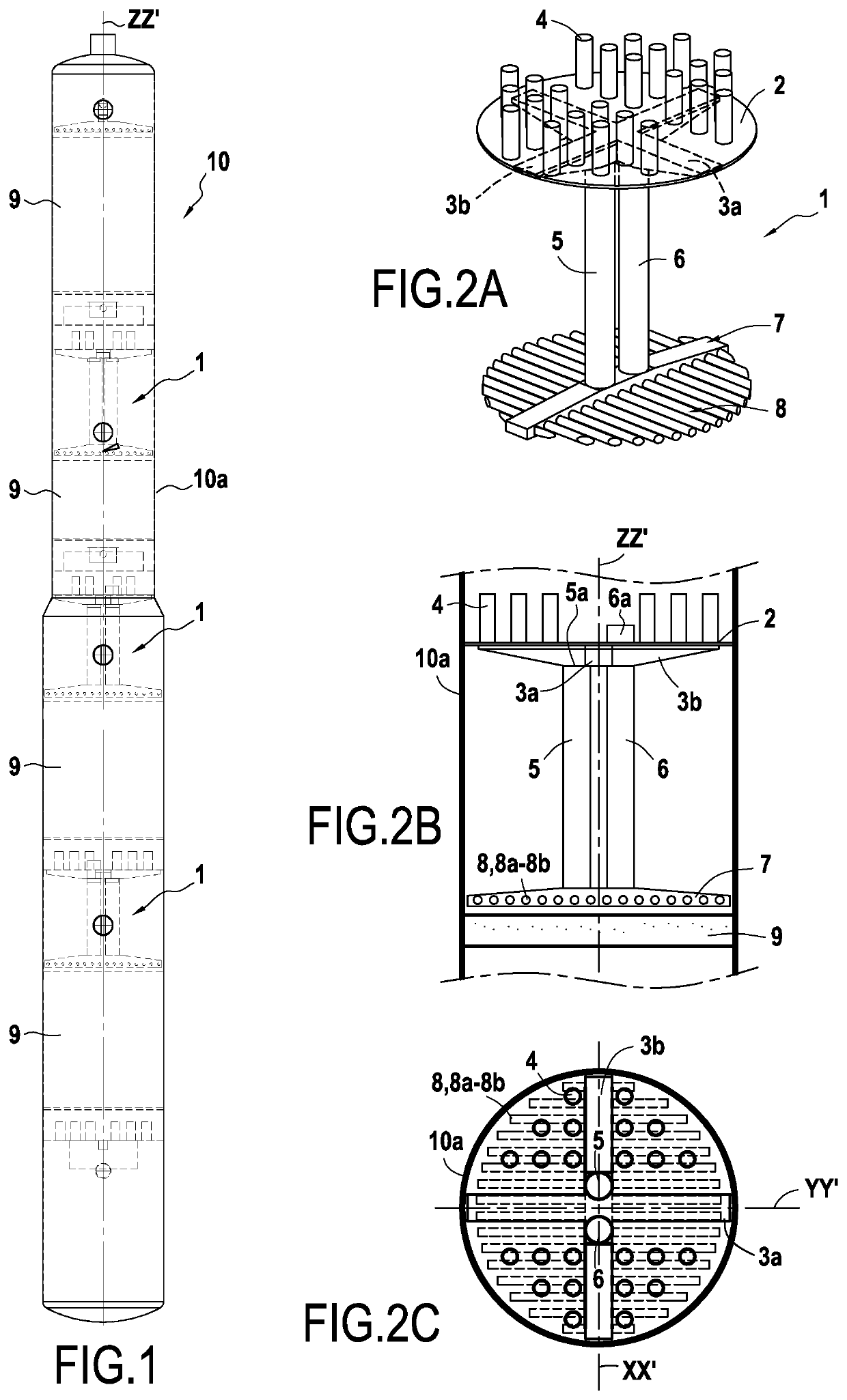
[0090]FIG. 1 shows a fractionating or phase separating column 10 having a cylindrical wall 10a and containing three liquid distribution devices 1 arranged axially above three respective packing beds 9, each occupying the entire circular section of the column. The packing of these beds may be of the “structured” type such as “Mellapak™” structured packing from the supplier SULZER (CH) or “FLEXIPAC®” packing from the supplier KOCH GLITSCH (USA) or “INTALOX®” or “IMTP®” random packing from the supplier KOCH GLITSCH (USA).

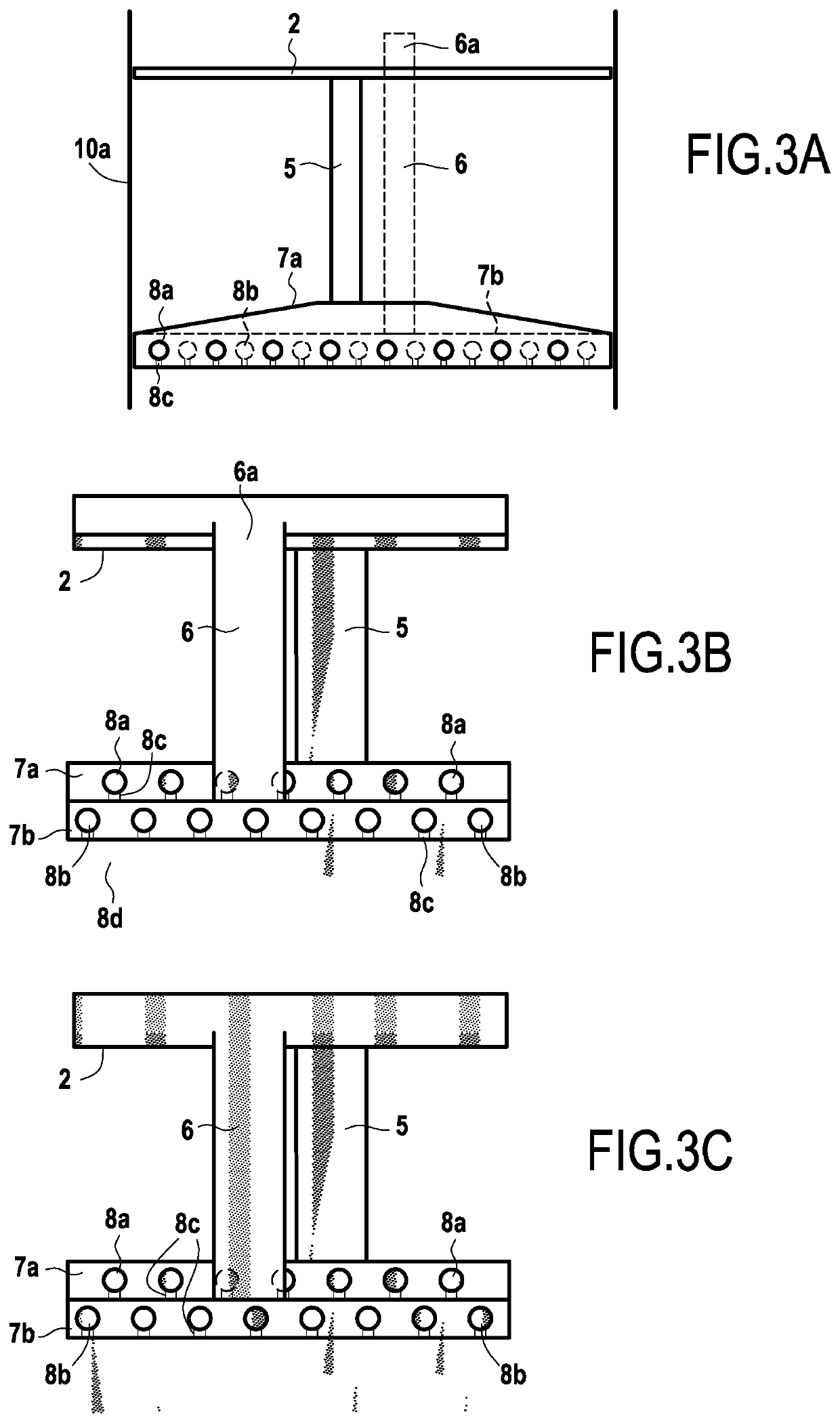
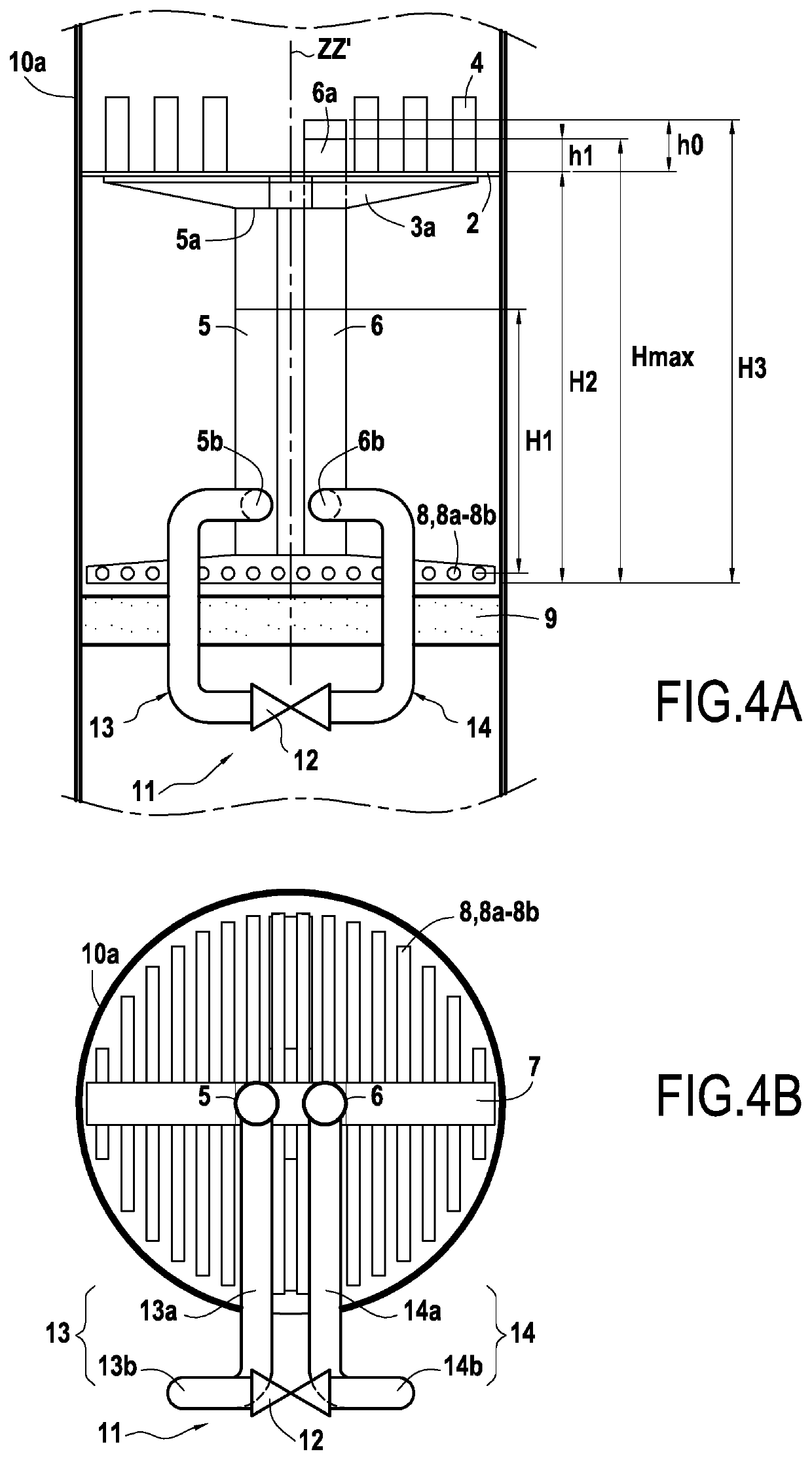
[0091]FIGS. 2A-2C, and also FIGS. 3A-3C and 4A-4B, show a double liquid distribution device 1 suitable for use in a fractionating or wash column 10 containing at least one packing bed 9 extending over the cross section of said column perpendicularly to the axial longitudinal direction ZZ′ of said column. From bottom to top, the liquid distribution device 1 comprises:

a high collector tray 2 of circular outline and of diameter equal to the diameter of the cylindrical wal...


PUM


Abstract

A double liquid distribution device is suitable for a fractionating or wash column comprising a high collector tray connected to a manifold support via at least two longitudinal liquid downflow ducts. The manifold support supports at least two series of transverse tubular manifolds and feeds liquid respectively to the first series of manifolds via a first longitudinal duct and to the second series of manifolds via a second longitudinal duct. Each manifold includes distribution orifices in its under face suitable for distributing the liquid onto the top face of the packing bed. The two longitudinal liquid downflow ducts are connected together in a low portion by a communication device fitted with a valve having controlled opening suitable for allowing the liquid to be transferred between the two longitudinal ducts in controlled manner.

Description

BACKGROUND OF THE INVENTION[0001]The present invention relates to the general field of liquid distributors on board a floating support and included in fractionating columns or in solvent wash columns or “scrubbers” and also in associated regeneration columns or in vertical coil heat exchangers used for liquefying natural gas, and in still more general manner in any type of vertical apparatus that is the seat of a gravity flow of a liquid phase that needs to be distributed in uniform manner in a zone arranged under the liquid distribution device and extending over a horizontal section of the gravity flow apparatus, the gravity flow apparatus being installed on board floating supports such as floating production storage and offloading units (FPSOs) or floating liquefied natural gas units (FLNGs).[0002]The fractionating or wash columns 10 shown in FIG. 1 are the seat of transfers of material and of energy between a vapor phase moving upwards and a liquid phase moving downwards under th...

Claims


Application Information

Patent Timeline
Patent Type & Authority Applications(United States)
IPC IPC(8): B01D3/00B01D53/18
CPCB01D53/185B01D3/324B01J8/0492F25J3/04927B01D3/16B01D3/008F25J2200/90B01D1/0005
Inventor DUPARC, BERTRANDRODIER, BENJAMINBOLOSIER, BORIS
Owner SAIPEM SPA
Why Eureka
Try Eureka