
Position estimation device and position estimation method

a wireless terminal and position estimation technology, applied in the direction of measurement devices, location information based services, instruments, etc., can solve the problems of difficult to accurately estimate limited communication range of nodes, difficult to correct a distance relational coefficient using a hop count, etc., to achieve the effect of improving the accuracy of the estimation of the position of a wireless terminal

Active Publication Date: 2020-05-14
PANASONIC INTELLECTUAL PROPERTY CORP OF AMERICA
View PDF0 Cites 2 Cited by
  • Summary
  • Abstract
  • Description
  • Claims
  • Application Information

AI Technical Summary

Benefits of technology

The present patent provides a device and method to improve the accuracy of position estimation in a wireless network where wireless terminals are distributed densely. This helps to accurately locate wireless terminals in the network.

Problems solved by technology

Further, a communication range of the nodes is limited, and the system is assumed to execute multi-hop communication.
In Unexamined Japanese Patent Publication No. 2005-348418, however, under an environment where nodes are close to each other, most of the packets reach from one node to another node in one hop among a plurality of nodes, and it is difficult to correct a distance relational coefficient using a hop count.
As a result, under an environment where a large number of nodes are densely distributed in a narrow range, it is difficult to highly accurately estimate a position of a wireless terminal.

Method used


Image

  • Position estimation device and position estimation method
  • Position estimation device and position estimation method
  • Position estimation device and position estimation method

Examples


first exemplary embodiment

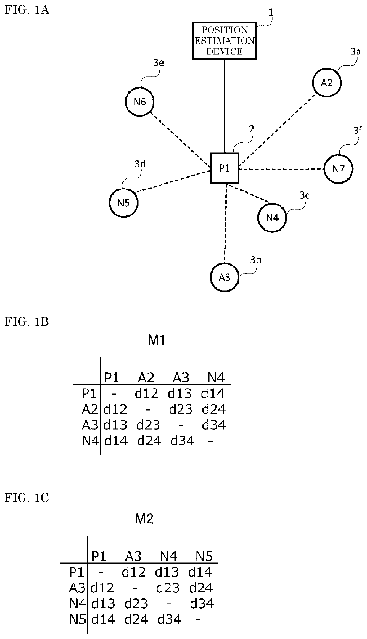
[0034]FIG. 1A is a diagram describing a position estimation device according to a first exemplary embodiment. FIG. 1A shows position estimation device 1, parent node (parent wireless terminal) 2, and child nodes (child wireless terminal) 3a to 3f. Moreover, FIG. 1B is a diagram showing distance matrix M1 that shows a distance between parent node 2 and each of child nodes 3a to 3c. FIG. 1C is a diagram showing distance matrix M2 that shows a distance between parent node 2 and each of child nodes 3b to 3d.

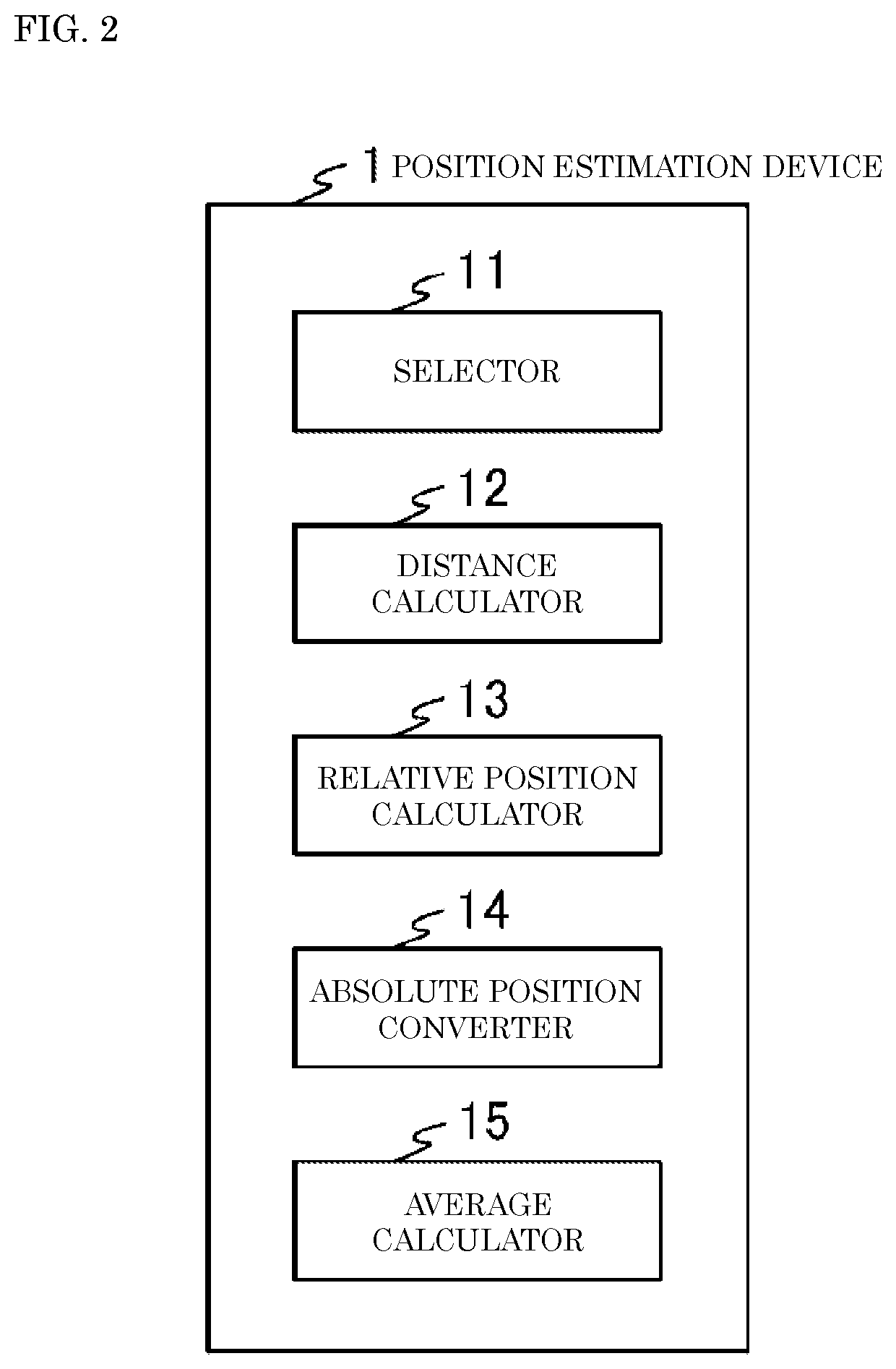
[0035]Parent node 2 and child nodes 3a to 3f are, for example, an access point and wireless sensor nodes or wireless terminals corresponding to wireless sensor nodes such as smart phones or tablet terminals. Position estimation device 1 communicates with child nodes 3a to 3f via parent node 2 to estimate the positions of child nodes 3a to 3f.

[0036]The position of parent node 2 is known. The positions of some of child nodes 3a to 3f are known. Here, the positions of child nodes 3a, ...

second exemplary embodiment

[0065]In a second exemplary embodiment, a case where wireless terminals that have gathered in a venue such as a concert venue or an athletic stadium are produced as a display that projects illumination or an image.

[0066]FIG. 5 is a diagram showing a system configuration of wireless communication system 100 according to the second exemplary embodiment. As shown in FIG. 5, wireless communication system 100 includes application control (AC) 101, position estimator (PE) 102, network control (NC) 103, and wireless terminals 104 to 110. Wireless terminal 104 is a parent node, and wireless terminals 105 to 110 are child nodes. Application control 101, position estimator 102, and network control 103 may be implemented by, for example, one personal computer (PC). Alternatively, application control 101, position estimator 102, and network control 103 each may be implemented by, for example, a different computer.

[0067]Application control 101 controls an input and output unit (described later) ...


PUM


Abstract

A position estimation device includes: a selector configured to select N wireless terminals and reselect N wireless terminals from M wireless terminals; a distance calculator configured to calculate distances among wireless terminals in a group consisting of a parent wireless terminal and the N wireless terminals based on information on power of radio signals of packets transmitted and received; a relative position calculator configured to calculate relative positions of the M wireless terminals based on the distances among the wireless terminals in the group for the N wireless terminals selected and reselected; and an absolute position converter configured to convert a relative position of a child wireless terminal into an absolute positon of the child wireless terminal based on the relative positions of the M wireless terminals and absolute positions of at least three of the M wireless terminals where the absolute positions are known.

Description

RELATED APPLICATIONS[0001]This application is a continuation of PCT International Application No. PCT / JP2018 / 021302, filed on Jun. 4, 2018, which claims the benefit of foreign priority of Japanese patent application 2017-142995 filed on Jul. 24, 2017, the contents all of which are incorporated herein by reference.BACKGROUND1. Technical Field[0002]The present disclosure relates to a position estimation device and a position estimation method for estimating a position of a wireless terminal.2. Background Art[0003]In Unexamined Japanese Patent Publication No. 2005-348418, a method for estimating a position of a node in an ad-hoc / sensor network.[0004]In the position estimation method in Unexamined Japanese Patent Publication No. 2005-348418, a position of a first node that recognizes the position is used for estimating a position of a second node that does not recognize the position. The first node generates and transmits a second packet that includes a distance relational coefficient c...

Claims


Application Information

Patent Timeline
Patent Type & Authority Applications(United States)
IPC IPC(8): H04W4/029G01S5/02G01S5/14H04W4/02
CPCG01S5/0289G01S5/145H04W4/029H04W4/023H04M11/00H04W64/00G01S5/14G01S5/02
Inventor SHIRAKATA, NAGANORITAKAHASHI, HIROSHINISHIYASU, KAZUMAMORITA, JUNICHI
Owner PANASONIC INTELLECTUAL PROPERTY CORP OF AMERICA
Learn More