Electrochemical cell

Active Publication Date: 2020-05-14
SEIKO INSTR INC
View PDF1 Cites 0 Cited by
  • Summary
  • Abstract
  • Description
  • Claims
  • Application Information

AI Technical Summary

Benefits of technology

The patent text describes an electrochemical cell with strip-shaped electrodes that are difficult to arrange with high density on the exterior body due to the simple shape after deformation and the complicated outer shape of the electrode when folding and bending a connection piece. The present invention aims to improve the degree of freedom in the shape and secure the capacity of the electrochemical cell.

Problems solved by technology

For this reason, depending on the shape of the exterior body, it is difficult to arrange the electrodes with a high density on the exterior body.
For this reason, the outer shape of the electrode is complicated and a gap is easily formed at the periphery of the electrodes in the exterior body.
Thus, depending on the shape of the exterior body, it is difficult to arrange the electrodes with a high density on the exterior body.

Method used


Image

  • Electrochemical cell
  • Electrochemical cell
  • Electrochemical cell

Examples


first embodiment

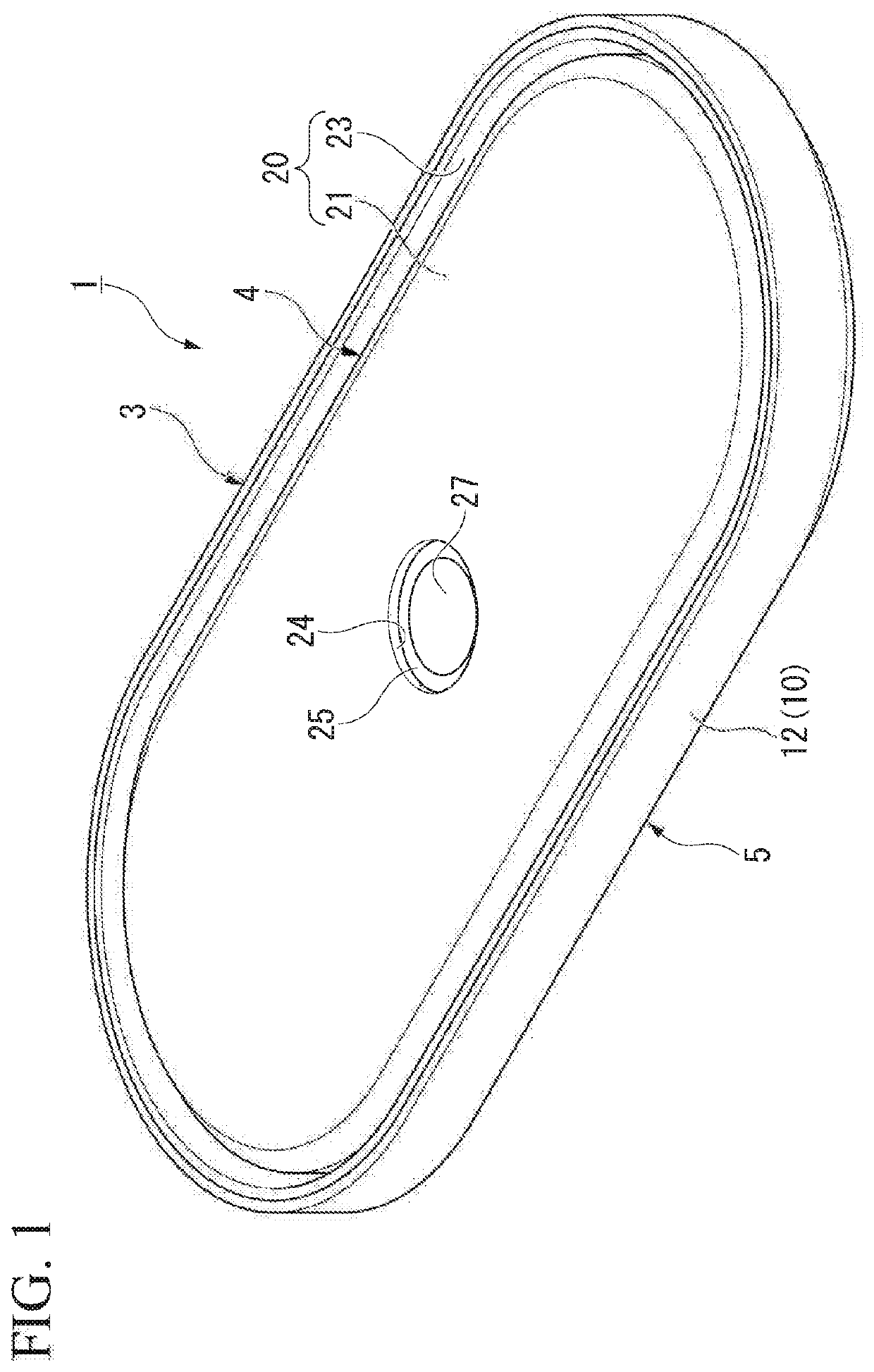
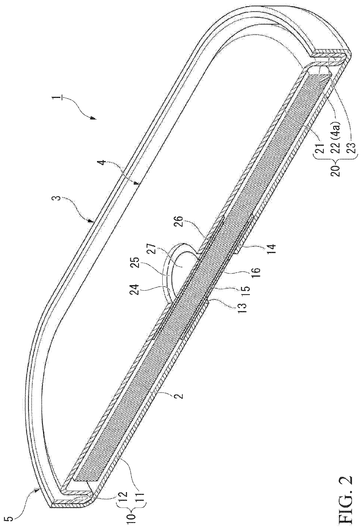
[0040]FIG. 1 is a perspective view of the battery of the embodiment. FIG. 2 is a cross-sectional view of the battery of the embodiment.

[0041]As shown in FIG. 1 and FIG. 2, a battery 1 is a battery having an oval shape in a plan view (a rounded rectangular shape). The battery 1 is provided with a laminated electrode body 2, an electrolyte solution (not shown) impregnated in the laminated electrode body 2, and an exterior body 3 in which the laminated electrode body 2 is housed.

[0042]The exterior body 3 is provided with a housing portion 4 in which the laminated electrode body 2 is housed, and a sealing portion 5 bent along an outer periphery 4a of the housing portion 4. The sealing portion 5 is bent along the outer periphery 4a of the housing portion 4 by drawing, for example.

[0043]In addition, the exterior body 3 is provided with a first container 10 and a second container 20 with the laminated electrode body 2 sandwiched therebetween. The first container 10 and the second container...

second embodiment

[0090]FIG. 8 is a cross-sectional view of a laminated electrode body of a second embodiment.

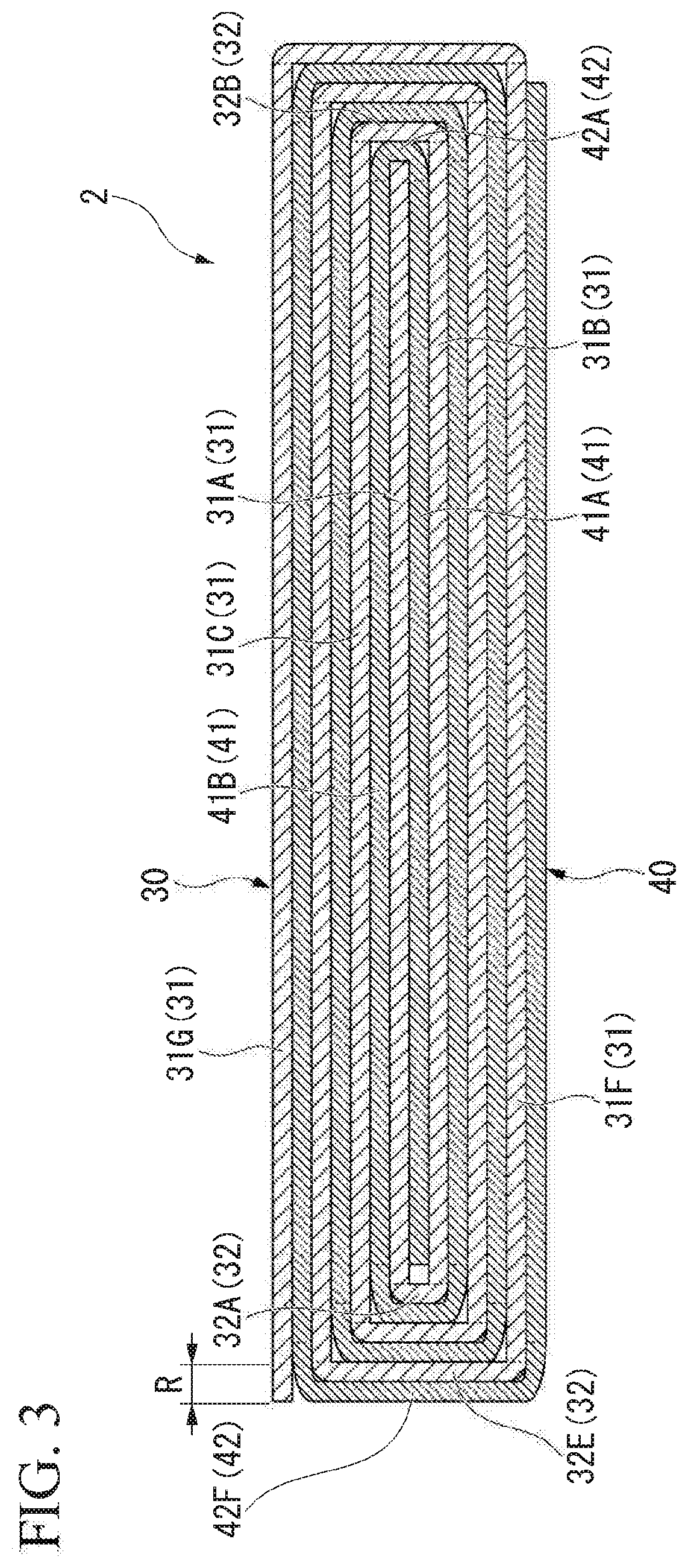
[0091]In the first embodiment shown in FIG. 3, the laminated electrode body 2 is densely wound around the winding center. In contrast, in the second embodiment shown in FIG. 8, a laminated electrode body 102 has a gap C at the winding center, which is the different point from the first embodiment. The configurations other than those described below are the same as those in the first embodiment.

[0092]As shown in FIG. 8, in the winding center of the laminated electrode body 102, a first negative electrode main body 31A and a first positive electrode main body 41A are arranged with an interval larger than the thickness of one layer of the separator 50 (see FIG. 4) in the laminating direction. As a result, the gap C is formed at the winding center of the laminated electrode body 102. The gap C is formed by pulling out a winding core 60, which will be descried later, from the laminated electrode b...


PUM


Abstract

A battery includes a negative electrode body wound to be flat. The negative electrode body has a plurality of negative electrode main bodies arranged in a line in a negative electrode connection direction in a developed state, and at least one negative electrode connection portion connecting a pair of negative electrode main bodies adjacent in the developed state among the plurality of negative electrode main bodies. The at leak one negative electrode connection portion is folded back such that the plurality of negative electrode main bodies overlap each other. A dimension of each of the plurality of negative electrode main bodies in the negative electrode connection direction decreases with separation from an outer end side negative electrode main body. A dimension of the at least one negative electrode connection portions in the negative electrode connection direction increases with separation from an inner end side negative electrode connection portion.

Description

RELATED APPLICATIONS[0001]This application claims priority to Japanese Patent Application Nos. 2018-213800 filed on Nov. 14, 2018 and 2019-161346 filed on Sep. 4, 2019, the entire contents of which are incorporated herein by reference.BACKGROUND OF THE INVENTION1. Field of the Invention[0002]The present invention relates to an electrochemical cell.2. Description of the Related Art[0003]In the related art, electrochemical cells such as lithium ion secondary batteries and electrochemical capacitors are widely used as power sources for small devices such as smartphones, wearable devices, and hearing aids.[0004]In such electrochemical cells, from the viewpoint of increasing the battery capacity, the charging current, and the discharging current, it is necessary to increase the area of the electrodes opposing each other in the electrochemical cell. As the structure of the electrochemical cell, structures are known in which a pair of strip-shaped electrodes are opposed to each other via a...

Claims


Application Information

Patent Timeline
IPC IPC(8): H01M10/0587H01M2/26H01M10/0525H01M50/548H01M50/553H01M50/562
CPCH01M10/0525H01M10/0587H01M2/263H01M10/0431H01M4/75H01M50/553H01M50/548H01M50/562H01M10/0436Y02E60/10Y02P70/50
Inventor KIMURA, NAGAYUKIWATANABE, SHUNJIKANNO, YOSHIMI
Owner SEIKO INSTR INC
Why Eureka
Try Eureka