Method for manufacturing a multi-ribbed wing-box of composite material with integrated stiffened panels and communicating bays

Active Publication Date: 2020-05-14
LEONARDO SPA
View PDF0 Cites 0 Cited by
  • Summary
  • Abstract
  • Description
  • Claims
  • Application Information

AI Technical Summary

Benefits of technology

The present invention provides a method for manufacturing a wing-box for aircraft that allows for a multi-ribbed wing-box of composite material that is suitable for a wet wing design. The method ensures that the structural and quality defects, such as thinning and resin accumulation, are avoided during the manufacturing process. The arrangement of support inserts allows for the manufacturing of a multi-ribbed wing-box with integrated stiffened panels and communicating bays, ensuring general stiffness and stability during the curing step.

Problems solved by technology

This conventional configuration is called ‘build-up’ configuration, and is characterized by significant disadvantages in terms of production costs, including a large number of parts to be manufactured and managed in the production system, a very onerous assembly process due to the large number of holes to be made and fastening members to be installed, as well as the inspections necessary to verify the absence of openings or space between the coupled parts, and the additional activities required during construction to apply any fillers needed to fill the aforesaid gaps, when present.
In addition, the so-called build-up configuration also entails significant drawbacks in the weight of the structure, which are badly tolerated in aeronautical applications, especially due to the increase in the operating cost of the aircraft, i.e. in fuel consumption.
The weight increase for these assemblies is essentially due to the unavoidable presence of holes in the coupling areas between the various elements.
In addition, for composite structures, the weight of the fastening members also has a negative effect, since it is greater than the weight of the portion of material removed.
This technology, while overcoming all the technical problems typical of the build-up configuration mentioned above, is characterized by significant geometric and configuration limitations that limit its applicability to solely horizontal stabilizers of commercial aircraft.
Specifically, multi-spar co-cured wing boxes are not sufficiently competitive, in terms of weight and cost, with respect to wing boxes in build-up configuration for structures for which a high resistance to torsion is required, such as wing boxes and vertical stabilizers boxes.
A further technical problem of this technology is that it is not applicable to configurations that provide for the presence, in addition to the spars, of additional reinforcement stringers, for the longitudinal stiffening of the structure.
Furthermore, according to the prior art, it is not possible to make wing boxes with highly curved aerodynamic profiles and / or with inner thickening or stiffening elements in a transverse direction (i.e., that extend in the direction of the length of the wing profile), or with the stringers interrupted in the longitudinal direction (i.e., perpendicular to the direction of the length of the wing profile) of the wing box, or to make a wing-box for a “wet wing”, that is a wing-box provided with openings between adjacent bays to allow passage of fuel between them.

Method used


Image

  • Method for manufacturing a multi-ribbed wing-box of composite material with integrated stiffened panels and communicating bays
  • Method for manufacturing a multi-ribbed wing-box of composite material with integrated stiffened panels and communicating bays
  • Method for manufacturing a multi-ribbed wing-box of composite material with integrated stiffened panels and communicating bays

Examples


Embodiment Construction

[0021]In the present context, the term ‘longitudinal’ indicates a direction substantially coincident or parallel with that of the main extension of the wing or of the empennage, while the term ‘transverse’ indicates a direction substantially perpendicular thereto, identifiable, in general, with a direction substantially coincident or parallel with that of a wing or empennage profile.

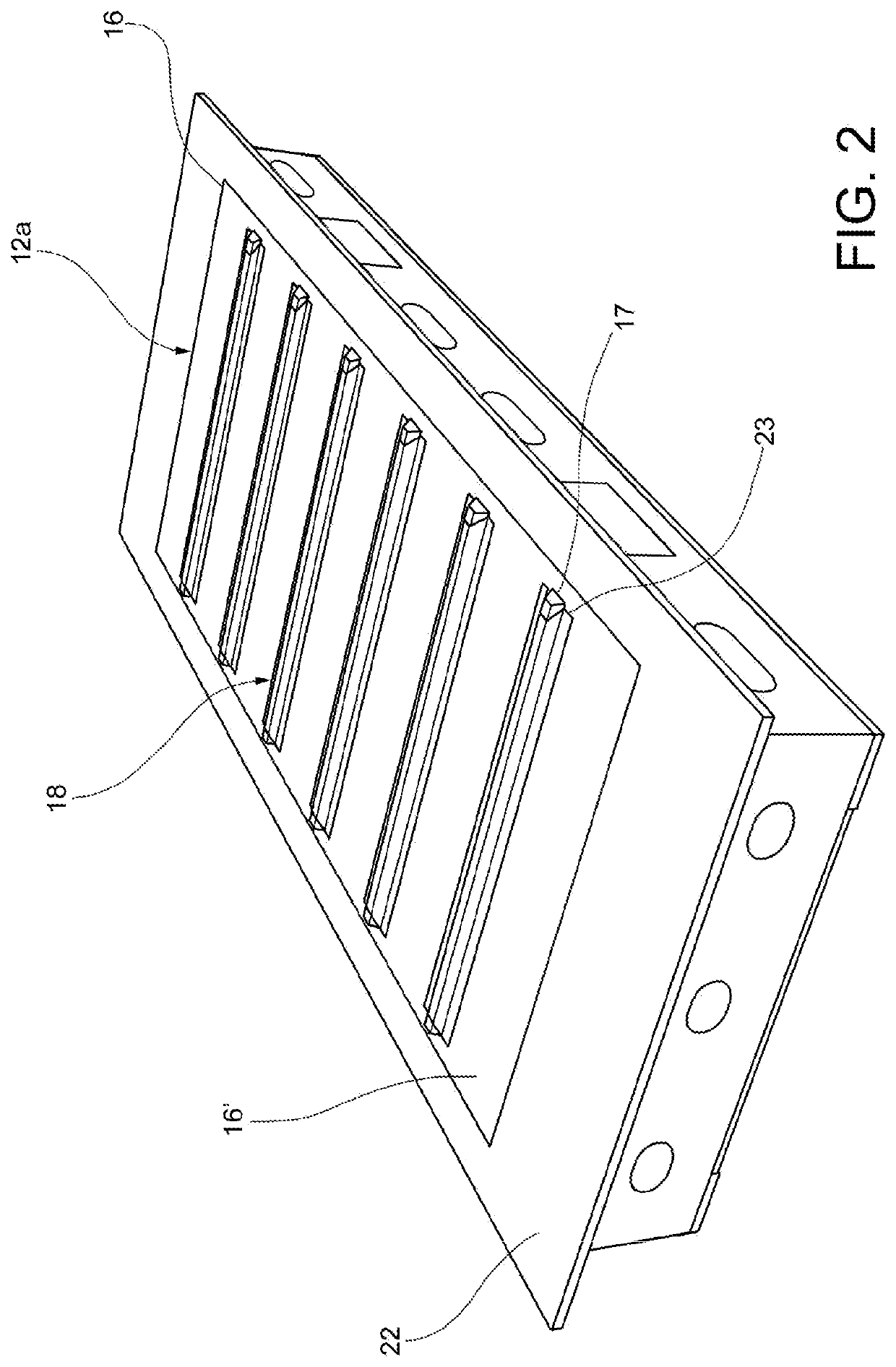
[0022]With reference to the Figures, a wing-box for aircraft as a whole is indicated with 10.

[0023]The wing-box 10 comprises a first panel 12a and a plurality of ribs 14 that separate different bays 11 from each other. The wing-box may be completed with a second panel 12b, placed on top of the bays 11 to close them, and that may be mechanically assembled in a known-per-se manner at the end of the process, or be connected by means of a curing process or of a “co-bonding” process by means of a supplementary adhesive ply.

[0024]The first panel 12a, the second panel 12b and the ribs 14 are made of composite m...


PUM

PropertyMeasurementUnit
Temperatureaaaaaaaaaa
Thicknessaaaaaaaaaa
Pressureaaaaaaaaaa

Abstract

A method for manufacturing a wing-box for aircraft comprises: arranging, on a curing surface, a first panel of composite material comprising a skin a plurality of longitudinal stringers, and arranging, on each stringer, a caul plate; arranging, on the first panel, pluralities of support inserts so that each support insert rests on a respective caul plate, and on the skin of the first panel, and arranging, on the first panel, a plurality of ribs of non-polymerized composite material, each rib comprising a plate, a first pair of flanges and a second pair of flanges arranged at opposed ends of the plate, and having openings on an edge of the plate, by placing the respective first pair of flanges on the first panel and the respective plurality of openings on the plurality of support inserts, and having the first panel and the plurality of ribs undergo a curing process in autoclave with vacuum bag.

Description

CROSS-REFERENCE TO RELATED APPLICATION[0001]This application claims priority to Italian Patent Application No. 102018000010326 filed Nov. 14, 2018, the entire contents of which is hereby incorporated in its entirety by reference.FIELD OF THE INVENTION[0002]The present invention relates in general to a method for manufacturing a structural part for aircraft. In particular, the invention relates to a method for manufacturing a multi-ribbed wing-box of composite material with integrated stiffened panels and communicating bays, that may be used as a structural wing-box in a so called ‘wet wing’, that is a wing used also as a fuel tank, or in a vertical or horizontal empennage.BACKGROUND OF THE INVENTION[0003]The configuration currently adopted for aeronautical boxes—for wings or empennages of fixed-wing aircraft—consists of a set of different primary structural components, such as, typically, two stiffened panels with longitudinal stringers, two longitudinal spars, a certain number of t...

Claims


Application Information

Patent Timeline
IPC IPC(8): B32B37/00B64F5/10B64C3/18B64C3/26B32B3/08B32B37/10B32B37/12B32B7/12
CPCB32B2262/106B64F5/10B32B2262/101B32B2260/046B64C3/34B32B2260/021B32B3/085B32B37/12B64C3/26B64C3/182B32B2605/18B64C3/187B32B37/10B32B7/12B64C3/185B32B37/0076B64C1/00B64C2001/0072B29D99/0014B29L2031/3085
Inventor IAGULLI, GIANNIRAFFONE, MARCORUSSOLILLO, ALBERTONANULA, TOMMASOTOTARO, GIUSEPPE
Owner LEONARDO SPA
Why Eureka
Try Eureka