
Venous ablation catheter and method

a catheter and vein technology, applied in the field of vein ablation, can solve the problems of skin necrosis, varicose veins, ulcers and wounds, extreme pain, and severe bleeding

Pending Publication Date: 2020-04-30
CHAGARLAMUDI ANIL K
View PDF0 Cites 1 Cited by
  • Summary
  • Abstract
  • Description
  • Claims
  • Application Information

AI Technical Summary

Benefits of technology

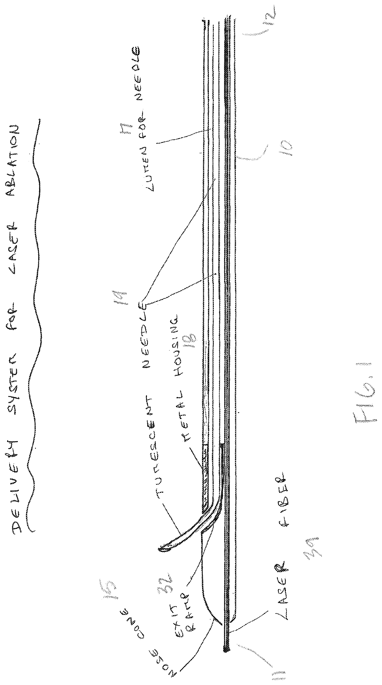
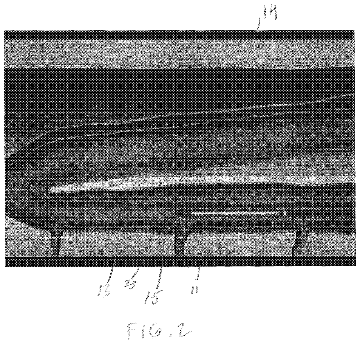
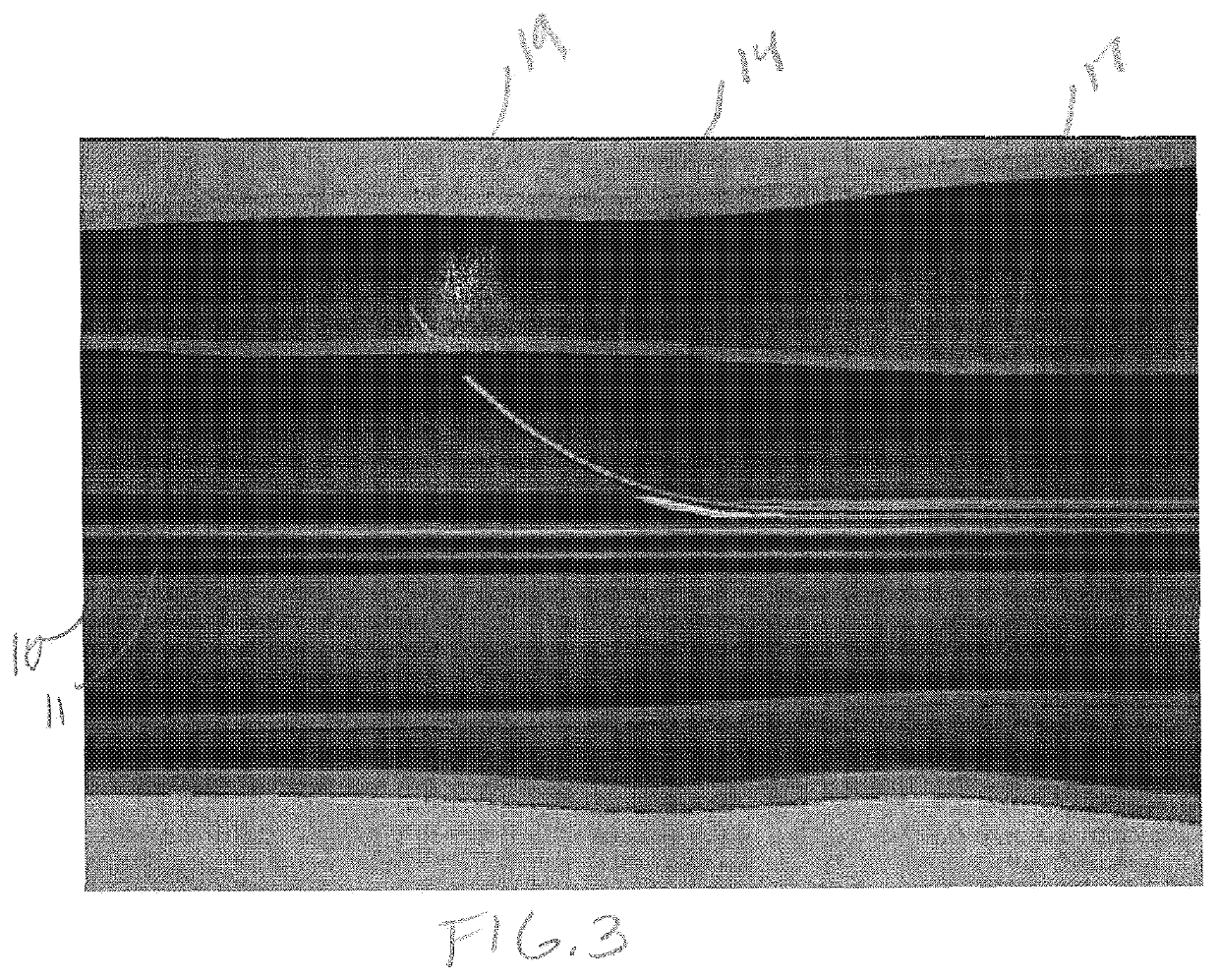
The patent is for an improved catheter device and method for ablating and injecting fluid into a vein. The device can inject fluid precisely around the vein using a needle that exits the catheter. The method requires fewer needle sticks in the patient, which reduces pain and recovery time. The device can also ablate and inject fluid simultaneously in adjacent segments of the vein. The technical effects include improved precision, reduced pain, and more efficient treatment.

Problems solved by technology

In severe cases, CVI can cause skin necrosis, varicose veins, ulcers and wounds.
Varicose veins can get thrombosed causing extreme pain or can rupture causing severe bleeding.
The high heat generated causes severe pain and can result in tissue injury.
The numerous needle sticks can be painful and leads to some patients failing to return for a second procedure, if needed.
The current method of injecting fluid around a vein takes a certain level of skill and finesse, but the current ablation procedures known in the art can be imprecise.
The current ablation procedures are even more difficult in obese patients or if the vein is deep seated.
The transcutaneous needle utilized in the procedure can also injure tissue, blood vessels and or nerves along its course causing bleeding, hematomas, and numbness.
Many patients have open wounds making the ablation procedure riskier and more difficult, while other patients prefer to receive anxiolytics and or sedatives prior to procedure which may have side effects.

Method used


Image

  • Venous ablation catheter and method
  • Venous ablation catheter and method
  • Venous ablation catheter and method

Examples


Embodiment Construction

[0018]The following detailed description is presented to enable any person skilled in the art to make and use the invention. For purposes of explanation, specific details are set forth to provide a thorough understanding of the present invention. However, it will be apparent to one skilled in the art that these specific details are not required to practice the invention. Descriptions of specific applications are provided only as representative examples. Various modifications to the preferred embodiments will be readily apparent to one skilled in the art, and the general principles defined herein may be applied to other embodiments and applications without departing from the scope of the invention. The present invention is not intended to be limited to the embodiments shown but is to be accorded the widest possible scope consistent with the principles and features disclosed herein.

[0019]The current invention is an improved method of treatment of incompetent saphenous veins through ab...


PUM


Abstract

An improved venous ablation catheter and method of use. More particularly, the present invention relates to a radio-frequency ablation catheter that ablates and injects tumescent from inside a vein simultaneously. The catheter device comprises a distal end, proximal end, a needle and lumen for the needle to pass through, and an interior housing. After the vein to be ablated is cannulated and the catheter device is advanced into the vein, the needle is advanced through the venous wall into the peri-venous sheath and tumescent fluid or other fluid or gas is injected around the vein through the needle. The vein segment that has been injected with tumescent is sequentially ablated with the catheter device, and the catheter device is then drawn a distance out of the vein. At this point, the needle can be advanced through the venous wall again injecting tumescent or other fluid. This process can be repeated until the treatment is completed without having to remove the catheter device from the vein, thus requiring only one needle stick and fewer office visits for the patient.

Description

CROSS-REFERENCE TO RELATED APPLICATIONS[0001]This application claims priority to U.S. Provisional Application No. 62 / 693,223 filed on Jul. 2, 2018, the contents of which are incorporated herein by reference in its entirety.FIELD OF THE INVENTION[0002]The present invention is in the field of ablation and related to delivering fluid around blood vessels from inside the lumen of the vessels. Specifically, the present invention is related to an improved ablation catheter that ablates and injects tumescent from inside a vessel simultaneously.BACKGROUND[0003]Venous ablation therapy is a well-known procedure. Chronic venous insufficiency (CVI) is the reflux of blood in the veins of lower extremities due to incompetent valves. CVI is very prevalent in the general population and affects 30-50 million people in United States. In CVI, the blood pools in the lower legs causing symptoms including, but not limited to, heaviness, burning, aching, restless legs, hyperpigmentation, and edema. In sev...

Claims


Application Information

Patent Timeline
Patent Type & Authority Applications(United States)
IPC IPC(8): A61B18/14A61M25/06
CPCA61M25/0606A61B2018/00577A61B2018/00404A61B18/1492A61B18/1477A61B2018/1425A61M5/158
Inventor CHAGARLAMUDI, ANIL K
Owner CHAGARLAMUDI ANIL K
Learn More