Thermal regenerator for exhaust system

a technology of exhaust system and regenerator, which is applied in the direction of engines, mechanical equipment, machines/engines, etc., can solve the problems of urea deposit formation from def injection, insufficient exhaust temperature to support efficient operation of scr catalyst,

Active Publication Date: 2020-04-23
FAURECIA EMISSIONS CONTROL TECH GERMANY
View PDF6 Cites 1 Cited by
  • Summary
  • Abstract
  • Description
  • Claims
  • Application Information

AI Technical Summary

Benefits of technology

[0010]An exemplary method comprises providing a housing defining an internal cavity and positioning a burner within the internal cavity where the burner provides a combustion chamber having an exhaust gas inlet, a fuel inlet, a combustion air inlet, and an outlet. The method further includes positioning at least one exhaust aftertreatment component within the internal cavity and directly coupling the at least one exhaust aftertreatment component to the outlet of the combustion chamber. The

Problems solved by technology

Under certain operating conditions, such as cold start conditions, exhaust temperatures are not initially high enoug

Method used


Image

  • Thermal regenerator for exhaust system

Examples


Embodiment Construction

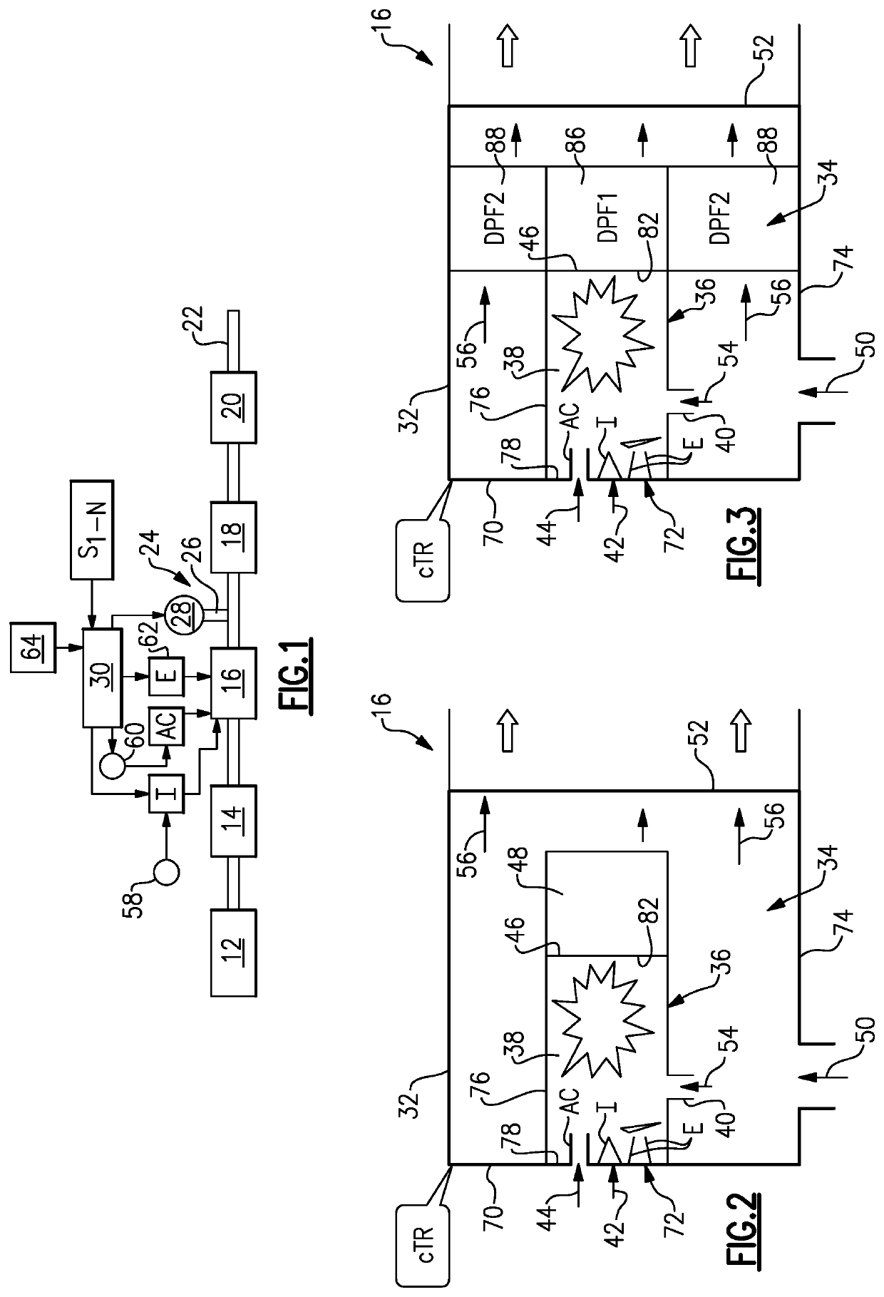
[0017]FIG. 1 shows a schematic representation of a vehicle exhaust system 10 that conducts hot exhaust gases generated by an engine 12 through various exhaust components to reduce emission and control noise as known. In one example configuration, the exhaust system 10 includes at least an upstream exhaust component 14 that is positioned downstream of the engine 12, a thermal regenerator 16 that is positioned downstream from the upstream exhaust component 14, and at least one additional exhaust aftertreatment component 18 that is positioned downstream of the thermal regenerator 16. In one example, the upstream exhaust component 14 comprises an exhaust manifold, turbocharger, a catalyst or one or more exhaust pipes that are connected to an upstream end of the thermal regenerator 16.

[0018]In one example, the at least one additional exhaust aftertreatment component 18 comprises a selective catalytic reduction (SCR) or SCR with a filter (SCRF) that is positioned downstream of the thermal...


PUM


Abstract

An exhaust component includes a housing defining an internal cavity and a burner positioned within the internal cavity. The burner provides a combustion chamber having an exhaust gas inlet, a fuel inlet, a combustion air inlet, and an outlet. At least one exhaust aftertreatment component is positioned within the internal cavity and is directly coupled to the outlet of the combustion chamber.

Description

BACKGROUND OF THE INVENTION[0001]A thermal system is used to elevate the temperature of exhaust gas to activate a selective catalytic reduction (SCR) catalyst in a vehicle exhaust system. The SCR catalyst reduces levels of NOx using ammonia as a reductant. The reducing agent, such as diesel exhaust fluid (DEF) for example, reacts with NOx to convert pollutants into nitrogen and water. Under certain operating conditions, such as cold start conditions, exhaust temperatures are not initially high enough to support efficient operation of the SCR catalyst. This can lead to urea deposit formation from the DEF injection. It is therefore desirable to provide a thermal management system that can ensure that the SCR catalyst is operating efficiently and optimally under all conditions.SUMMARY OF THE INVENTION[0002]In one exemplary embodiment, and exhaust component includes a housing defining an internal cavity and a burner positioned within the internal cavity. The burner provides a combustion...

Claims


Application Information

Patent Timeline
IPC IPC(8): F01N3/20F01N3/035F01N3/10
CPCF01N3/2066F01N3/106F01N2610/02F01N3/103F01N3/035F01N2560/06F01N2240/14F01N3/2033F01N3/021F01N13/0093F01N9/00F01N2900/1404F01N2900/1602Y02A50/20Y02T10/12Y02T10/40
Inventor PARRISH, TONY R.
Owner FAURECIA EMISSIONS CONTROL TECH GERMANY
Why Eureka
Try Eureka