
Apparatus and methods for determining icing risk in wind turbines

a wind turbine and ice risk technology, applied in the direction of motors, engine control, wind energy generation, etc., can solve the problems of affecting the power production efficiency and force of the rotor, the likelihood of ice build-up on the wind turbine blade is high, and the subsequent removal of ice may not occur at a sufficiently fast rate to counter the re-formation of ice on the blades. , to achieve the effect of increasing (or preventing further decrease of) wind turbine power

Active Publication Date: 2020-04-16
VESTAS WIND SYST AS
View PDF0 Cites 6 Cited by
  • Summary
  • Abstract
  • Description
  • Claims
  • Application Information

AI Technical Summary

Benefits of technology

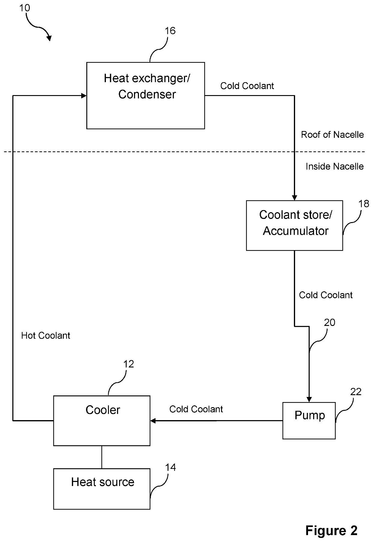
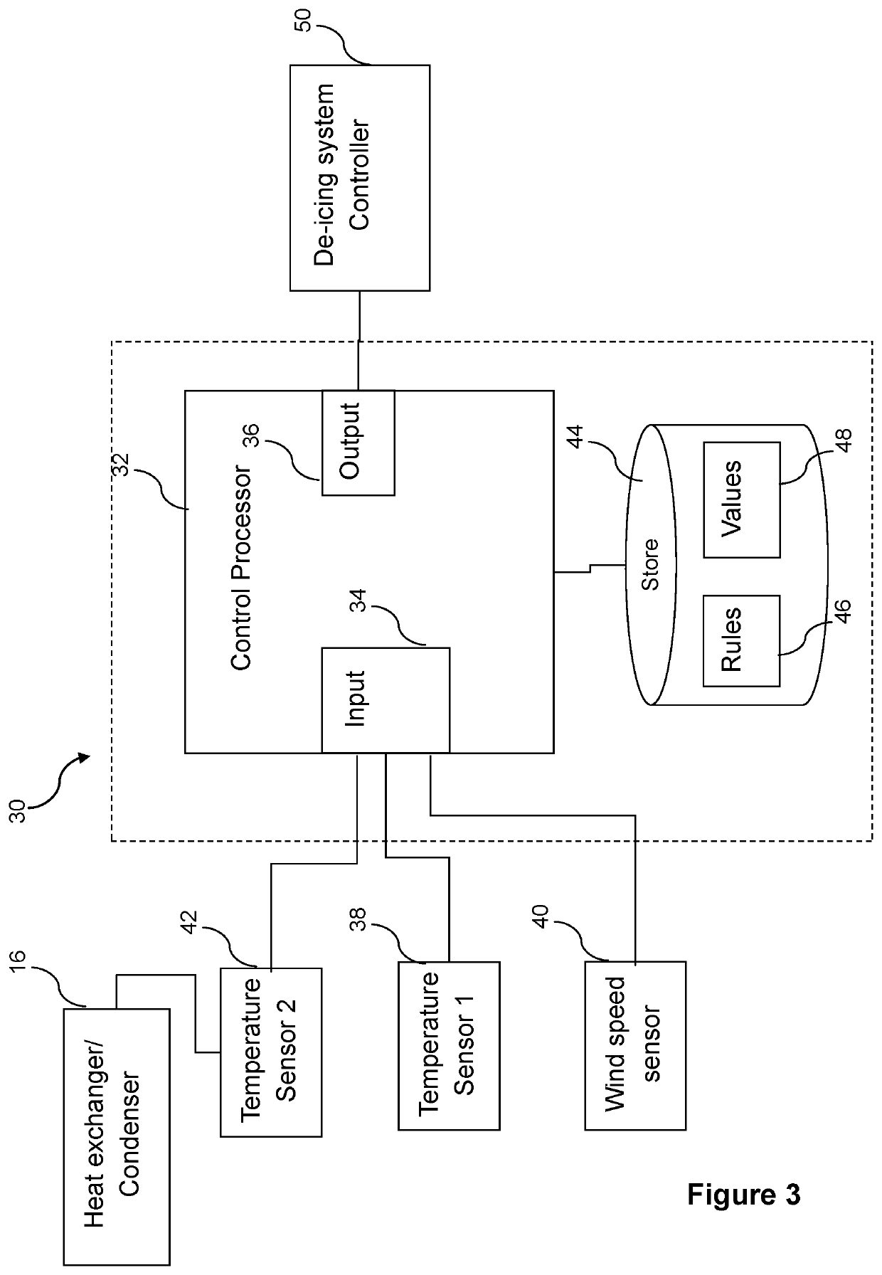
The patent describes a system for monitoring the temperature of a wind turbine's cooling system to detect the level of liquid water content and the associated risk of icing on the wind turbine blades. This system uses existing equipment already installed on the wind turbine, such as the cooling system, without the need for additional sensors. By monitoring the temperature difference between the heat exchanger and the wind turbine external environment, the system can automatically determine if the risk of icing is high enough to affect power production and activate the de-icing or anti-icing system to reduce the risk. The technical effect of the patent is to provide a cost-effective and efficient solution for detecting and preventing wind turbine blade ice damage.

Problems solved by technology

However, due to the low temperatures experienced in these locations during the winter, the likelihood of ice build-up on the wind turbine blades is high.
The build-up of ice on the turbine blades adversely affects the power production efficiency and forces on the rotor.
These triggering or activation mechanisms typically require a substantial build-up of ice before the decrease in output power of the wind turbine is sufficient to satisfy the necessary threshold conditions, since a large amount of ice is required to have formed in order to cause the necessary drop in output power.
However, in particularly cold conditions, even after the de-icing system is activated, the subsequent removal of ice may not occur at a sufficiently fast rate to counter the re-formation of the ice on the blades.

Method used


Image

  • Apparatus and methods for determining icing risk in wind turbines
  • Apparatus and methods for determining icing risk in wind turbines
  • Apparatus and methods for determining icing risk in wind turbines

Examples


Embodiment Construction

[0030]A specific embodiment of the invention will now be described in which numerous specific features will be discussed in detail in order to provide a thorough understanding of the inventive concept as defined in the claims. However, it will be apparent to the skilled person that the invention may be put in to effect without the specific details and that in some instances, well known methods, techniques and structures have not been described in detail in order not to obscure the invention unnecessarily.

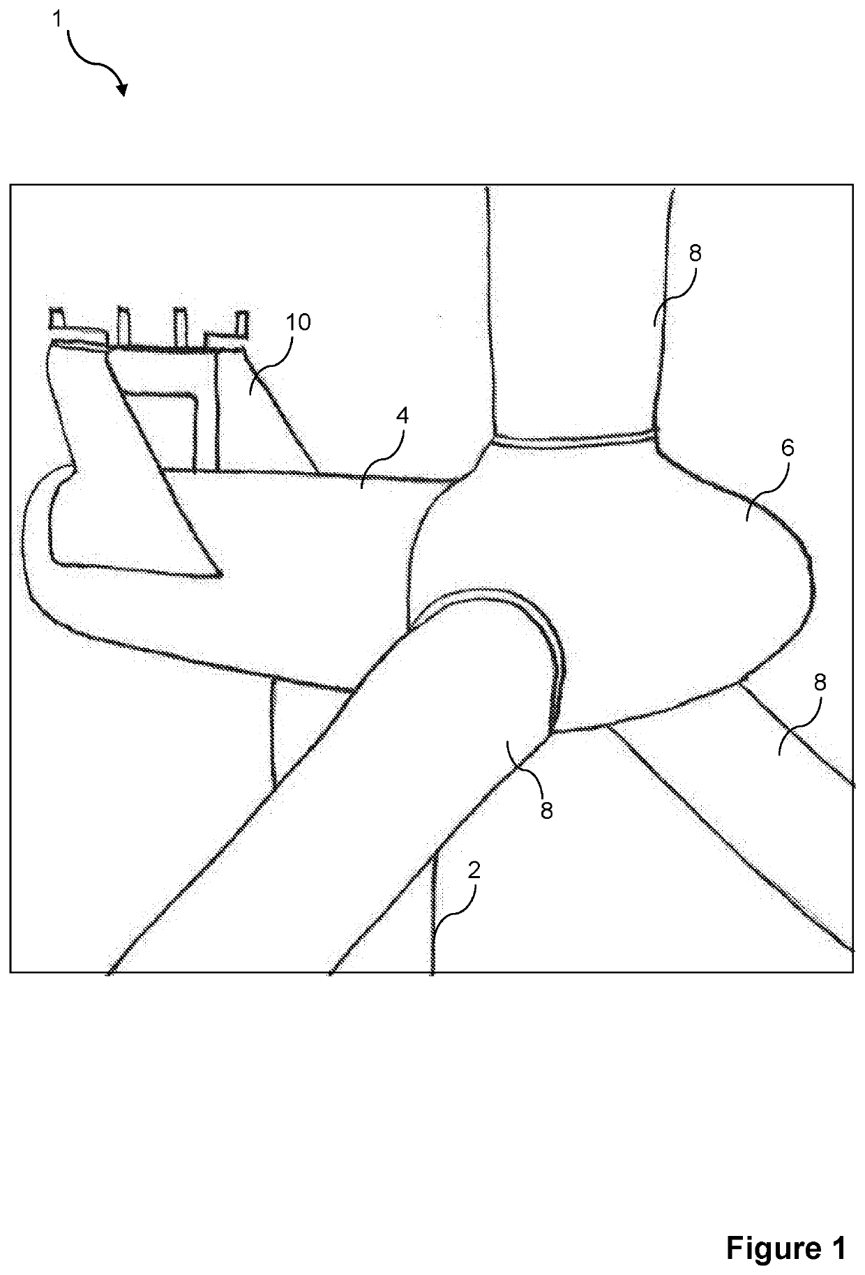
[0031]In order to place the embodiments of the invention in a suitable context, reference will firstly be made to FIG. 1, which illustrates schematically a portion of a typical wind turbine in which an apparatus for determining icing risk and for controlling a sub-system of the wind turbine according to an embodiment of the present invention may be implemented.

[0032]The wind turbine 1 comprises a tower 2, a nacelle 4 rotatably coupled to the top of the tower 2, a rotating hub 6 moun...


PUM


Abstract

According to an embodiment of the present invention there is provided an apparatus for controlling a sub-system of a wind turbine. The apparatus comprises a cooling system comprising first and second heat exchangers, and a fluid circuit arranged to enable a coolant to flow between the first and second heat exchangers; and a processor. The processor is configured to: monitor one or more operational parameters of the cooling system; determine an icing risk based on the one or more operational parameters; and generate a control signal for output to the wind turbine sub-system in dependence on the determined icing risk.

Description

TECHNICAL FIELD[0001]Aspects of the present invention relate to an apparatus and method for determining icing risk in wind turbines, and more particularly to systems and methods for triggering the activation of de-icing systems for wind turbines in dependence on the determined icing risk.BACKGROUND[0002]Wind turbines that are to be installed in cold climates make up a large proportion of the global wind turbine market, as such climates tend to have high wind resources, particularly during the winter. However, due to the low temperatures experienced in these locations during the winter, the likelihood of ice build-up on the wind turbine blades is high. The build-up of ice on the turbine blades adversely affects the power production efficiency and forces on the rotor.[0003]Various types of de-icing (and anti-icing) systems and methods have already been implemented in cold climate wind turbines. For example, a controlled blade acceleration / deceleration to shake off the ice is sometimes...

Claims


Application Information

Patent Timeline
IPC IPC(8): F03D80/40F03D17/00F03D9/25
CPCF03D80/40F03D17/00F03D9/25F05B2270/323F03D80/60Y02E10/72
Inventor GRUNNET, JACOB DELEURANTHYBO, CLAUSNIELSEN, JOHNNY
Owner VESTAS WIND SYST AS
Learn More