
Method of manufacturing an inkjet print head and an inkjet print head with induced crystal phase change actuation

a manufacturing method and technology of inkjet print head, which are applied in the direction of printing, electrical equipment, electric/electrostrictive/magnetostrictive devices, etc., can solve the problem of significant change in the shape of the crystal material, and achieve reliable and controllable manufacturing methods.

Active Publication Date: 2020-04-09
CANON PRODN PRINTING HLDG BV
View PDF0 Cites 0 Cited by
  • Summary
  • Abstract
  • Description
  • Claims
  • Application Information

AI Technical Summary

Benefits of technology

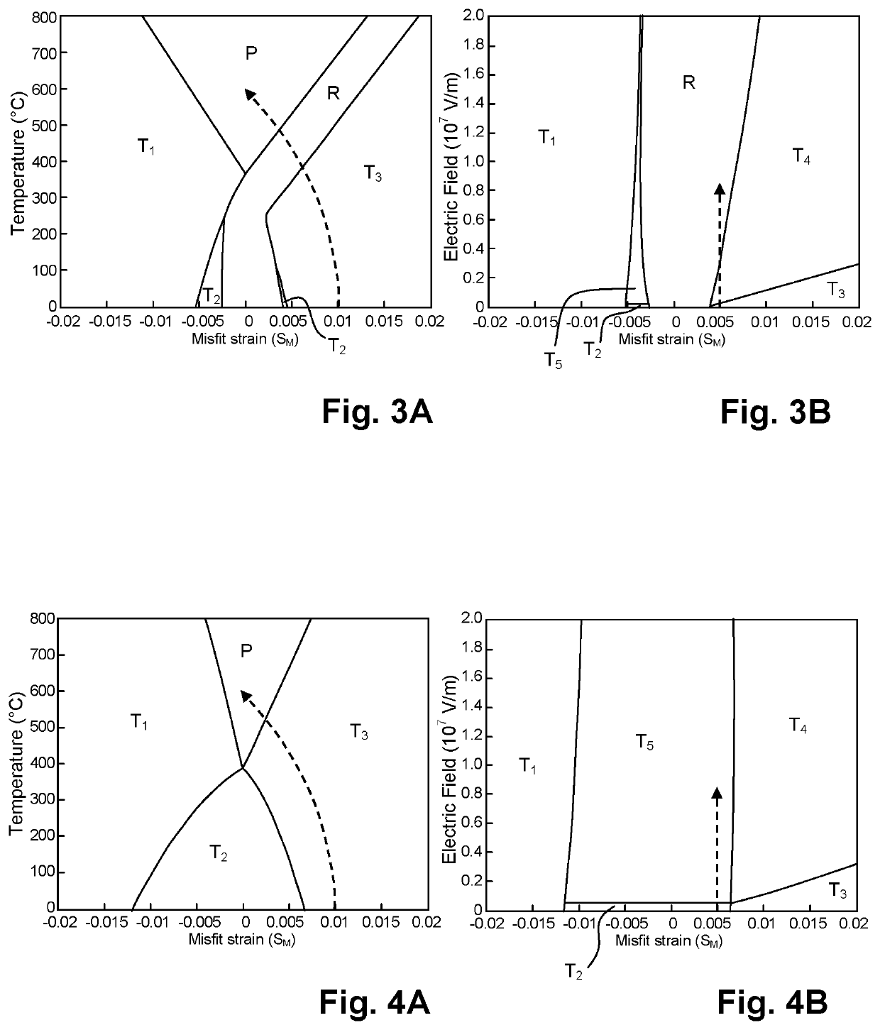
This patent describes a way to create an inkjet print head that can change the phase of ink to induce printing. A phase diagram is used to select the optimal misfit strain and electric field that can cause the phase change. By using this method, the print head can operate reliably and with greater control over the ink printing process. Additionally, the reduced power consumption of the print head is possible because the method allows for a phase change with low electric fields.

Problems solved by technology

Heating the piezoelectric crystal material will affect the crystal phase of the material, resulting in a significant change of the shape of the crystal material.

Method used


Image

  • Method of manufacturing an inkjet print head and an inkjet print head with induced crystal phase change actuation
  • Method of manufacturing an inkjet print head and an inkjet print head with induced crystal phase change actuation
  • Method of manufacturing an inkjet print head and an inkjet print head with induced crystal phase change actuation

Examples


Embodiment Construction

[0033]The present invention will now be described with reference to the accompanying drawings, wherein the same reference numerals have been used to identify the same or similar elements throughout the several views.

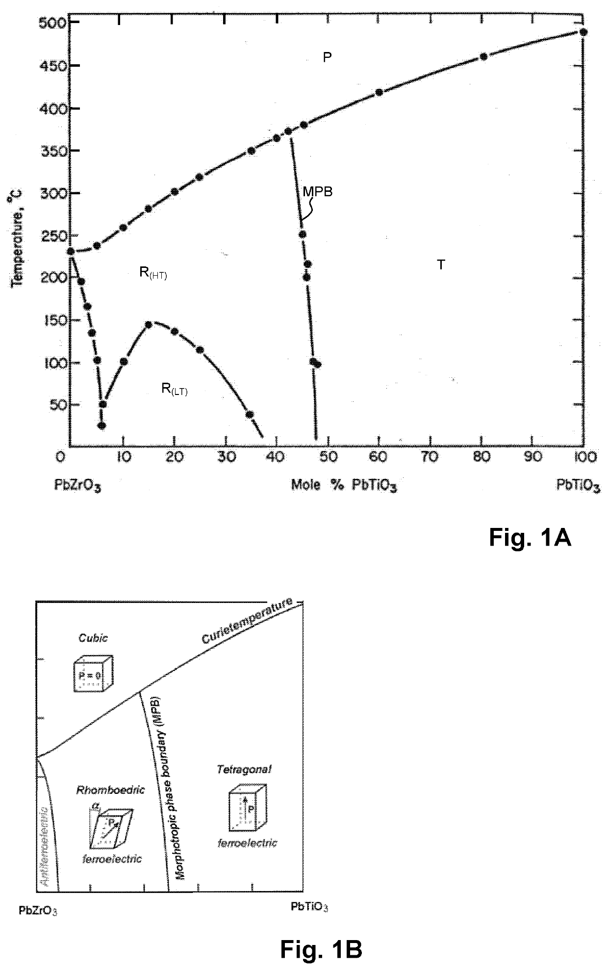
[0034]FIGS. 1A and 1B are phase diagrams of PZT, which is a piezoelectric material, in particular a ferroelectric material and more in particular a perovskite material. In the illustrated phase diagram, the horizontal axis represents a composition of the PZT material. The PZT material comprises Lead (Pb), Oxygen (O), Zirconium (Zr) and Titanium (Ti). The PZT material has a crystal structure comprising unit cells, wherein each unit cell comprises Lead, Oxygen and either Zirconium (PbZrO3) or Titanium (PbTiO3). Certain properties of the PZT material depend on the ratio of the number of unit cells comprising Zirconium and the number of unit cells comprising Titanium. The horizontal axis of the phase diagram presented in FIGS. 1A and 1B represents the percentage of unit cell...


PUM


Abstract

A method for manufacturing an inkjet print head includes determining a misfit strain—electric field crystal phase relation for at least one composition of a piezoelectric material; selecting a misfit strain value and a composition of the piezoelectric material based on the determined misfit strain—electric field crystal phase relation for said at least one composition; and based on the selected misfit strain and the selected composition of the piezoelectric material, forming a base layer and an actuator stack on the base layer, the actuator stack including the piezoelectric material, wherein the base layer and the actuator stack have predetermined properties providing the selected misfit strain value and the selected composition. Thus, an inkjet print head having a piezoelectric actuator that is operated on the basis of a crystal phase change is reliably manufacturable.

Description

CROSS-REFERENCE TO RELATED APPLICATIONS[0001]This application is a Continuation of International Application No. PCT / EP2018 / 065228, filed on Jun. 8, 2018, and for which priority is claimed under 35 U.S.C. § 120, and which claims priority under 35 U.S.C. § 119 to Application No. 17177308.8, filed in Europe on Jun. 22, 2017. The entirety of each of the above-identified applications is expressly incorporated herein by reference.BACKGROUND OF THE INVENTION1. Field of the Invention[0002]The present invention generally pertains to an inkjet print head having a piezoelectric crystal actuator, wherein an actuation is induced by inducing a crystal phase change by application of an electric field. Further and in particular, the present invention pertains to a method for manufacturing such an inkjet print head.2. Description of Related Art[0003]An inkjet print head having a piezoelectric crystal actuator, wherein an actuation is induced by inducing a crystal phase change by application of an e...

Claims


Application Information

Patent Timeline
Patent Type & Authority Applications(United States)
IPC IPC(8): H01L41/083B41J2/16B41J2/14H01L41/187H01L41/08H01L41/09H01L41/25H10N30/50H10N30/00H10N30/03H10N30/20H10N30/853
CPCH01L41/0838B41J2/161H01L41/25H01L41/1876H01L41/0973B41J2/14233H01L41/081H10N30/2047H10N30/8554H10N30/04H10N30/706H10N30/508H10N30/03
Inventor BLOM, FRANCISCUS R.
Owner CANON PRODN PRINTING HLDG BV
Learn More