
Batteries and methods for handling a detected fault condition

a technology of fault condition and battery, applied in the direction of batteries, safety/protection circuits, sustainable manufacturing/processing, etc., can solve the problems of fault condition occurring, first cell of the communications device battery being compromised, etc., to prevent or reduce the undesirable safety and reliability problems

Inactive Publication Date: 2020-04-02
MOTOROLA SOLUTIONS INC
View PDF0 Cites 1 Cited by
  • Summary
  • Abstract
  • Description
  • Claims
  • Application Information

AI Technical Summary

Benefits of technology

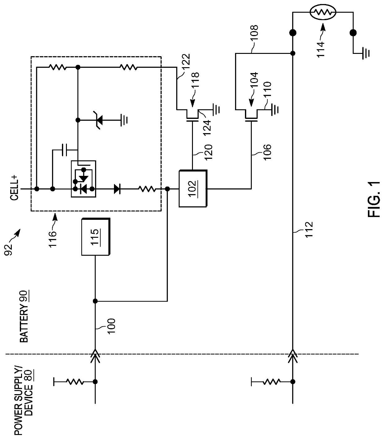
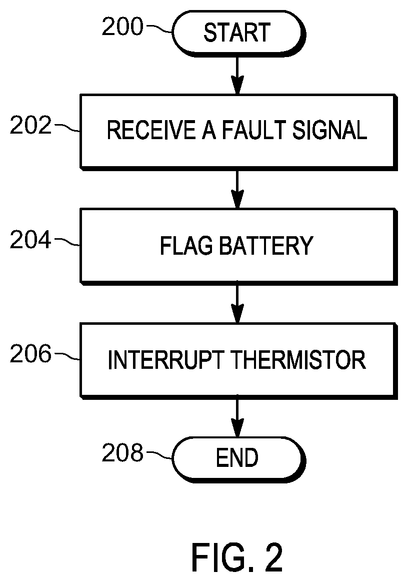
The patent is about methods, batteries, and communication devices that can handle fault conditions to prevent battery charging above a desired rate. The methods involve receiving a fault signal indicating a fault condition and disabling charging upon receiving the signal. The fault signal can be received at a data line of the battery and can flag that a switch has been activated or a latch has been activated. The technical effects include preventing battery overcharging and ensuring reliable and safe operation.

Problems solved by technology

A fault condition can occur, for example, due to damaged cells, failed weld connections, overheating, and other circumstances.
The fault signal indicates that at least a first cell of the communications device battery has been compromised.

Method used


Image

  • Batteries and methods for handling a detected fault condition
  • Batteries and methods for handling a detected fault condition
  • Batteries and methods for handling a detected fault condition

Examples


Embodiment Construction

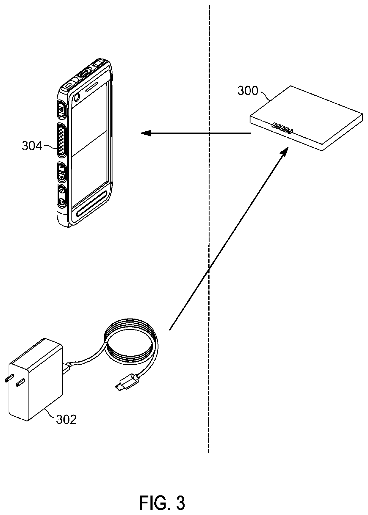
[0021]Batteries disclosed herein can be used to power devices and can be charged by power supplies. Unless indicated otherwise, a “device” can be any item that a battery can power, a “power supply” is anything that can charge a battery, and a “battery” is an object that can retain an electric charge and can include one or more cells and circuitry. A battery may be contained in a user-removable battery for a communications device. A “communications device” may include a cellular telephone, radio, walkie-talkie, or other device used to send and / or receive electronic communications. First responders may desire user-removable batteries so that a battery can be replaced when it is depleted.

[0022]When a battery is plugged into a power supply for charging, preventing each of the cells of the battery from charging beyond a desired rate can increase safety and reliability of the battery. For example, the desired rate may be 1 C, the rate it takes to charge the battery in 1 hour. Sometimes th...


PUM

PropertyMeasurementUnit
conductiveaaaaaaaaaa
temperatureaaaaaaaaaa
electric currentaaaaaaaaaa

Abstract

In accordance with some embodiments, a battery includes a cell and a thermistor coupled to a monitor line and a switch. The monitor line is operable to send signals to the communications device or battery corresponding to a temperature of at least a portion of the battery. A data line is coupled to a decoder. The decoder is coupled to the switch, wherein the decoder is operable to activate the switch, thereby interrupting the thermistor. In accordance with some embodiments, a method includes receiving a fault signal at a data line of the battery, the fault signal indicating that at least a first cell of the communications device battery has been compromised. The method includes interrupting a thermistor by activating a switch coupled to a decoder coupled to the data line, thereby simulating that the temperature of at least a portion of the battery has reached an outer limit.

Description

BACKGROUND OF THE INVENTION[0001]Batteries can have a single cell or multiple cells and can be arranged in parallel or in series. Batteries can power devices, such as portable communication devices. Each cell in a battery may receive electric current from a power supply or may deliver current to a device the battery is powering. In a fault condition in a battery, one or more cells are not being charged by a power supply at their normal rate or are not powering a device at their normal rate. A fault condition can occur, for example, due to damaged cells, failed weld connections, overheating, and other circumstances. When a fault condition occurs, and the battery is connected to be charged by a power supply, the current to a cell or cells and the charge rate can increase beyond normal limits. Such an increase can prevent the battery from operating reliably or safely.SUMMARY[0002]To prevent or reduce the undesirable safety and reliability issues that occur when a fault condition occurs...

Claims


Application Information

Patent Timeline
Patent Type & Authority Applications(United States)
IPC IPC(8): H01M10/48H01M10/04G06F1/28
CPCH01M10/486H01M10/0445G06F1/28H01M2200/106H01M2200/105H01M10/425H01M2010/4278H02J7/00309Y02E60/10H01M50/581Y02P70/50
Inventor ARENDELL, SCOTT J.KERFOOT, JR., ROY L.TARABOULOS, MARK C.FLOWERS, DONALD L.HERRMANN, JOHN E.
Owner MOTOROLA SOLUTIONS INC
Learn More