
LED driver with ability to operate at arbitrarily low input voltages

Active Publication Date: 2020-03-12
MAXIM INTEGRATED PROD INC
View PDF3 Cites 2 Cited by
  • Summary
  • Abstract
  • Description
  • Claims
  • Application Information

AI Technical Summary

Benefits of technology

The patent text describes methods for improving the performance and applicability of LED drivers by operating at low input voltages. This is achieved by incorporating a voltage comparator that can compare the input voltage to a predetermined threshold and is responsive to changes in voltage levels. The comparator uses a hysteresis function to prevent quick switching and minimize noise. The technical effects of this invention are improved performance and reliability of LED drivers, particularly in low-voltage applications.

Problems solved by technology

In various situations, an LED driver may have very low supply voltage which prevents the driver from providing adequate voltage to power the LED current regulation circuit.
However, the use of a charge-pump requires the addition of further external components, such as additional capacitor, and introduces another switching frequency into the system which may be an EMI hazard.
Large-value capacitors are physically large and expensive, and therefore may drive up overall cost or physical size to the LED driver.

Method used


Image

  • LED driver with ability to operate at arbitrarily low input voltages
  • LED driver with ability to operate at arbitrarily low input voltages

Examples


Embodiment Construction

[0016]In the following description, for purpose of explanation, specific details are set forth in order to provide an understanding of the present invention. The present invention may, however, be practiced without some or all of these details. The embodiments of the present invention described below may be incorporated into a number of different electrical components, circuits, devices, and systems. Structures and devices shown in block diagram are illustrative of exemplary embodiments of the present invention and are not to be used as a pretext by which to obscure broad teachings of the present invention. Connections between components within the figures are not intended to be limited to direct connections. Rather, connections between components may be modified, re-formatted, or otherwise changed by intermediary components.

[0017]When the specification makes reference to “one embodiment” or to “an embodiment” it is intended mean that a particular feature, structure, characteristic,...


PUM


Abstract

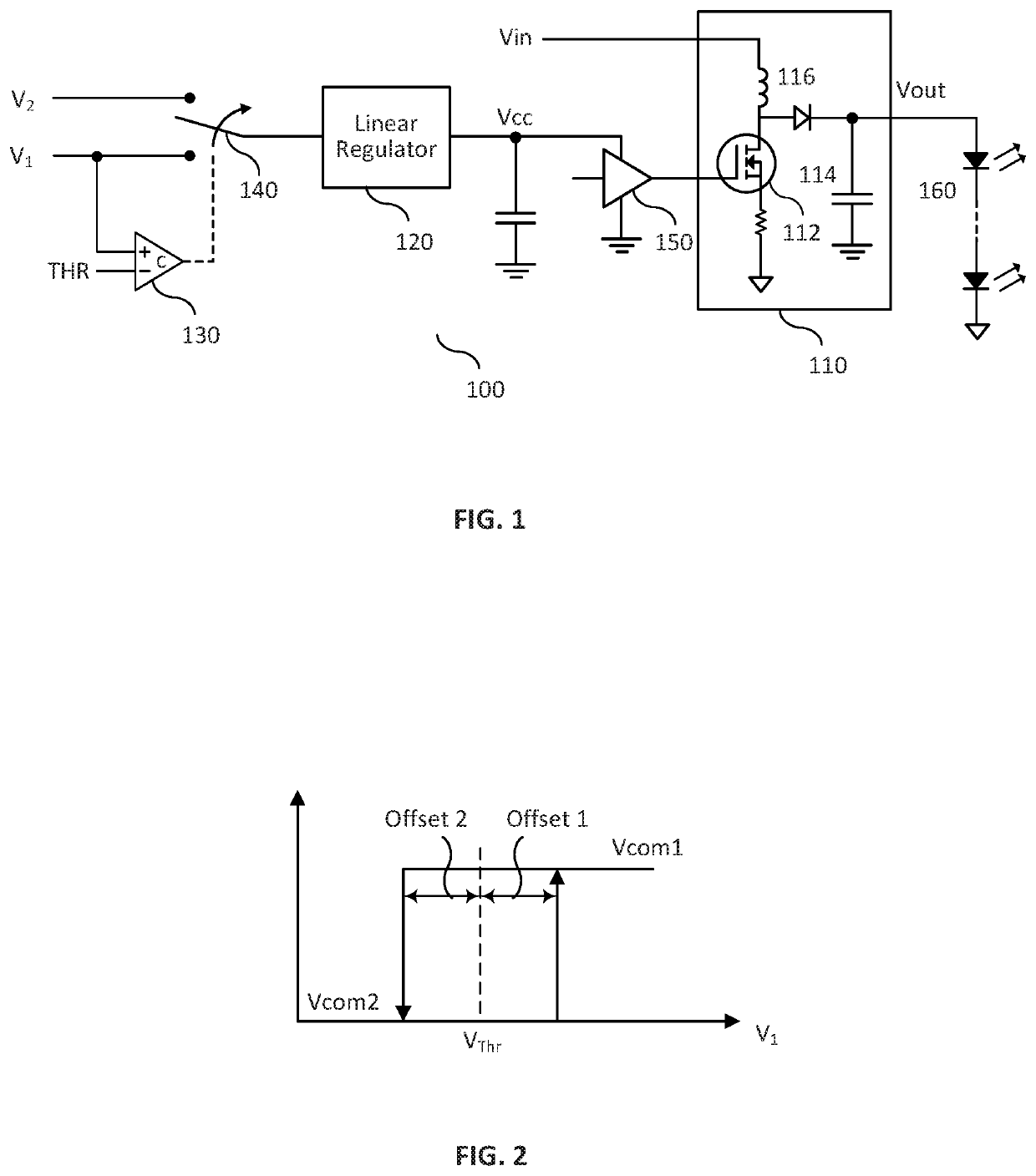
An LED driver with ability to operate at low input voltages is disclosed. The LED driver comprises a boost converter to boost an input voltage to a desired output voltage to power one or more LED strings. The boost converter incorporates a first controllable switch, such as a metal-oxide-semiconductor field-effect transistor (MOSFET), IGBT, etc., for output voltage control. The boost converter receives input from an external source, such as a battery voltage, as power source for voltage boost operation. The first controllable switch couples to a gate driver powered by a linear regulator, which switchably couples to different voltage sources via a second switch to ensure that the gate driver is able to provide enough voltage for switching the first controllable switch.

Description

CROSS-REFERENCE TO RELATED APPLICATION[0001]This application claims the priority benefit under 35 USC § 119(e) to U.S. Provisional Patent Application No. 62 / 729,172, entitled “LED DRIVER WITH ABILITY TO OPERATE AT ARBITRARILY LOW INPUT VOLTAGES,” listing as inventor Philip Anthony Murphy, and filed Sep. 10, 2018. The aforementioned patent document is incorporated by reference herein in its entirety.TECHNICAL FIELD[0002]The present disclosure relates generally to LED drivers, and more specifically to LED drivers with ability to operate at low input voltages.BACKGROUND OF THE INVENTION[0003]A light-emitting diode (LED) is a semiconductor light source used in various applications such as aviation lighting, automotive headlamps, advertising, traffic signals, camera flashes, LED-backlit displays, etc. Compared to traditional incandescent light sources, LEDs have many advantages, including lower energy consumption, longer lifetime, improved physical robustness, smaller size, and faster sw...

Claims


Application Information

Patent Timeline
IPC IPC(8): H05B33/08F21V23/00H05B44/00
CPCF21V23/003H05B45/37H05B45/395H02M1/08H02M1/0006H05B45/38Y02B20/30
Inventor MURPHY, PHILIP ANTHONY
Owner MAXIM INTEGRATED PROD INC
Learn More