Angular magnetic field sensor for a scanner

a magnetic field sensor and scanner technology, applied in the direction of instruments, measurement devices, using radiation, etc., can solve the problems of inability to monitor the radiation angle of the laser light, large installation space for the multiple lasers, and high cost of the technique, so as to achieve the effect of increasing the radiation angle and lateral resolution

Inactive Publication Date: 2020-03-12
BLICKFELD GMBH
View PDF2 Cites 3 Cited by
  • Summary
  • Abstract
  • Description
  • Claims
  • Application Information

AI Technical Summary

Benefits of technology

[0025]The combination of the magnet and the angular magnetic field sensor makes it possible to precisely monitor the rotation of the deflection unit based on the torsion. The angle, at which the light is deflected, can thereby be monitored precisely. The angle of radiation of the light can thereby be monitored precisely. The lateral resolution, for example of a LIDAR measurement, can thereby be increased. This can be particularly desirable in the scanner comprises two scanning units, each having a corresponding elastic element and a deflection unit, on which an optical path of the light is deflected sequentially. There may be increased imprecision in the angle of radiation there, namely without the corresponding monitoring.

Problems solved by technology

Such techniques, however, are expensive and require significant installation space for the multiple lasers.
In addition, a resolution along the direction of the multiple lasers is typically comparatively limited.
In addition, with highly integrated reference implementations, it may oftentimes not be possible to monitor the angle of radiation of the laser light, or only possible to a limited extent.

Method used


Image

  • Angular magnetic field sensor for a scanner
  • Angular magnetic field sensor for a scanner
  • Angular magnetic field sensor for a scanner

Examples


Embodiment Construction

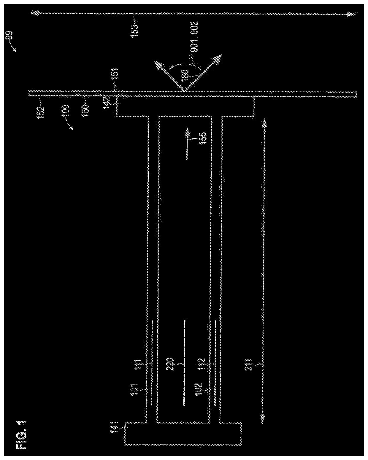
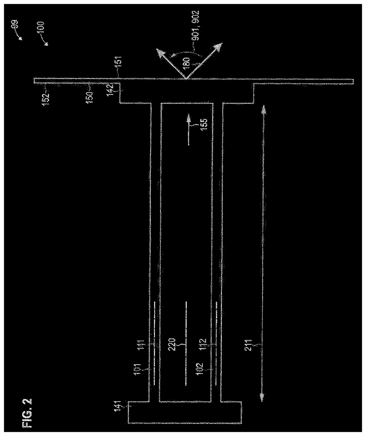
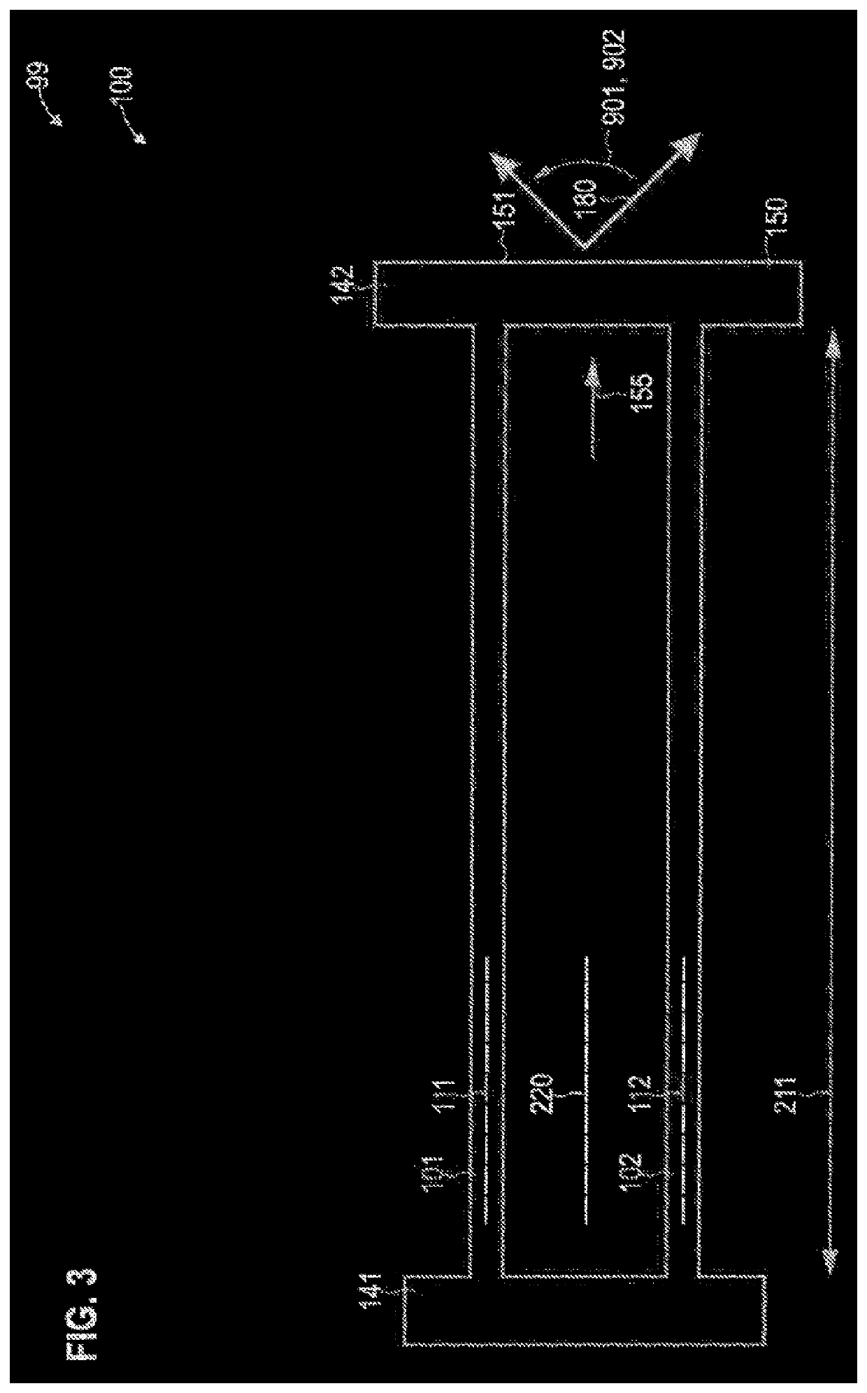
[0059]The previously described properties, features, and advantages of this invention as well as the type and manner as to how they are achieved will become more clearly and noticeably understandable in the context of the following description of the exemplary embodiments, which are explained in greater detail in connection with the drawings.

[0060]In the following, the present invention is explained in greater detail by means of preferred embodiments, with reference to the drawings. The same reference numerals refer to equivalent or similar elements in the figures. The figures are schematic representations of various embodiments of the invention. Elements shown in the figures are not necessarily shown to scale. Rather, the various elements shown in the figures are reflected such that their function and general purpose will be understandable to one skilled in the art. Connections and couplings between functional units and elements shown in the figures can also be implemented as a dir...


PUM


Abstract

A scanner (90) comprises a scanning unit (99, 99-1, 99-2) having an elastic element (101, 101-1, 101-2, 102, 102-1, 102-2), which extends between a base (141) and a deflection unit (142, 150), wherein the scanning unit (99, 99-1, 99-2) is set up to deflect light (180) at the deflection unit (142, 150) at different angles (901, 902) by means of torsion (502) of the elastic element (101, 101-1, 101-2, 102, 102-1, 102-2), a magnet (660) which is set up to generate a stray magnetic field, and an angular magnetic field sensor (662) which is arranged in the stray magnetic field and is set up to output a signal indicative of the torsion (502).

Description

TECHNICAL AREA[0001]The various examples relate generally to a scanner for light. In particular, various examples relate to a scanner for laser light, which can be used, for example, for LIDAR measurements.BACKGROUND[0002]The distance measurement of objects is desirable in various fields of technology. For example, it can be desirable in connection with applications of autonomous driving, detecting objects in the environment of vehicles, and particularly in determining a distance to objects.[0003]One technique for the distance measurement of objects is the so-called LIDAR technology (known as light detection and ranging or sometimes also LADAR in English). In this process, pulsed laser light is emitted from an emitter. The objects in the environment reflect the laser light. These reflections can then be measured. By determining the travel time of the laser light, a distance to objects can be determined.[0004]In order to detect the objects in the environment with spatial resolution, ...

Claims


Application Information

Patent Timeline
Patent Type & Authority Applications(United States)
IPC IPC(8): G01S7/481G01S17/06G01B7/30G02B26/08G02B26/10
CPCG01B7/30G01S7/4817G02B26/101G02B26/0858G01S17/06G01S17/42G02B26/0833G02B26/105G01L3/102
Inventor PETIT, FLORIAN
Owner BLICKFELD GMBH
Why Eureka
Try Eureka