Gas sensor

a technology of gas sensor and connector electrode, which is applied in the field of gas sensor, can solve the problems of connector electrode corrosion and short circuit between the connector electrod

Active Publication Date: 2020-02-27
NGK INSULATORS LTD
View PDF0 Cites 2 Cited by
  • Summary
  • Abstract
  • Description
  • Claims
  • Application Information

AI Technical Summary

Benefits of technology

The patent text describes a gas sensor that has a water-penetration reduction portion on one of its sides to prevent water from entering the sensor. This portion is located close to the front end and runs longitudinally. The sensor has a minimum length of 0.5 mm or more for this portion to effectively reduce water penetration. The water-penetration reduction portion has a gap region where water cannot exist, which further reduces the capillarity of water in the sensor. This helps to protect the sensor from water damage. Additionally, the text suggests that having a smaller length for the water-penetration reduction portion can reduce the area of the exposed side of the sensor, which is not covered by the porous layer. This makes the sensor more compact and easier to use.

Problems solved by technology

In such a case, water and the components dissolved in water, such as sulfuric acid, cause rusting and corrosion of the connector electrode and a short circuit between the connector electrodes.

Method used


Image

  • Gas sensor
  • Gas sensor
  • Gas sensor

Examples


experimental example 1

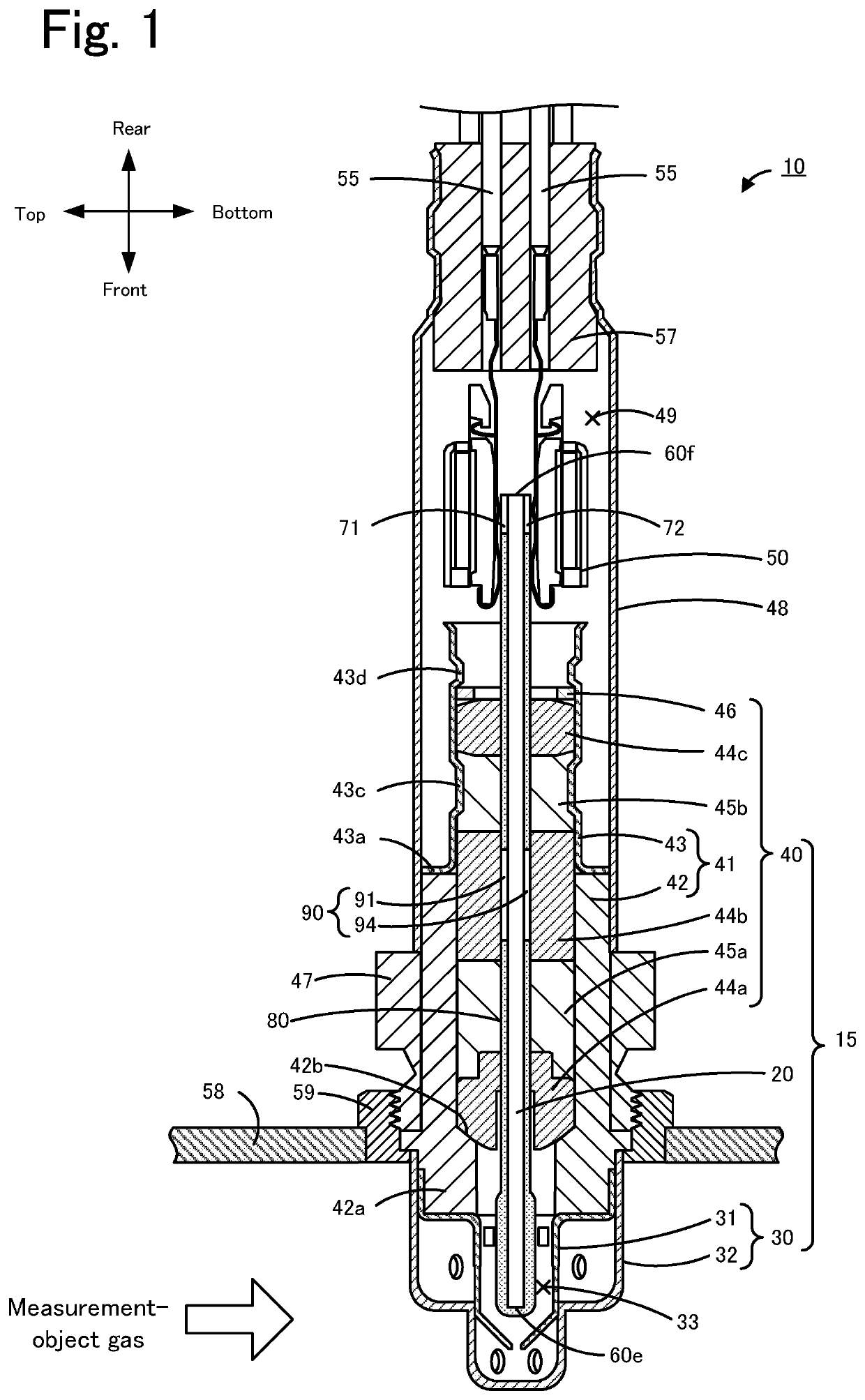
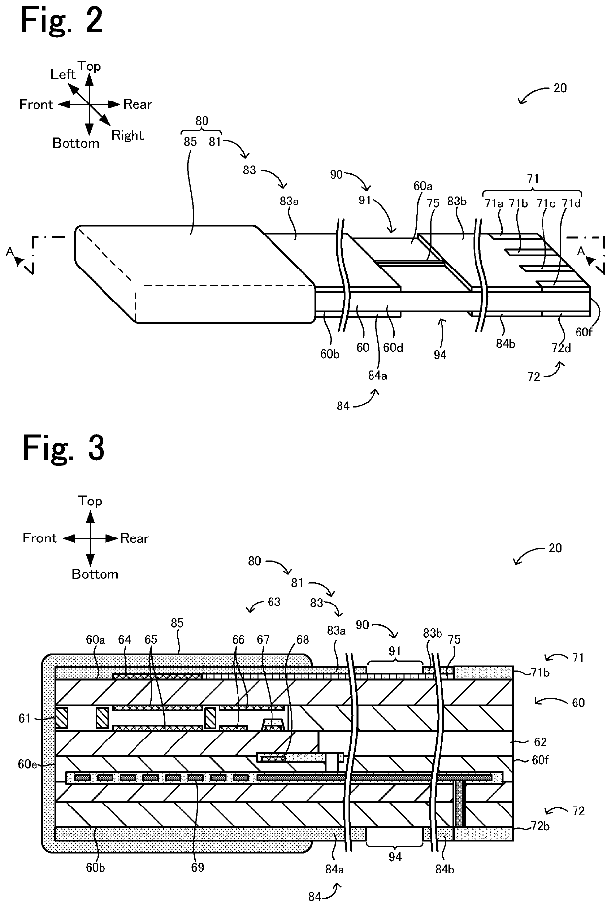
[0082]In Experimental example 1, a sensor element that was the same as the sensor element 20 illustrated in FIGS. 2 to 5 was prepared, and a gas sensor 10 that included this sensor element was prepared. Note that, in Experimental example 1, the positional relationship between the insulator 44b and the water-penetration reduction portion 90 was changed from the above-described embodiment illustrated in FIG. 6 as illustrated in FIG. 8. The sensor element 20 of the Experimental example 1 was prepared in the following manner. First, zirconia particles containing 4 mol % yttria serving as a stabilizer were mixed with an organic binder and an organic solvent. The resulting mixture was formed into six ceramic green sheets by tape casting. Patterns of electrodes and the like were printed in each of the green sheets. In addition, unbaked porous layers that were to be formed into the first inner porous layer 83 and the second inner porous layer 84 after baking were formed by screen printing. ...

experimental example 2

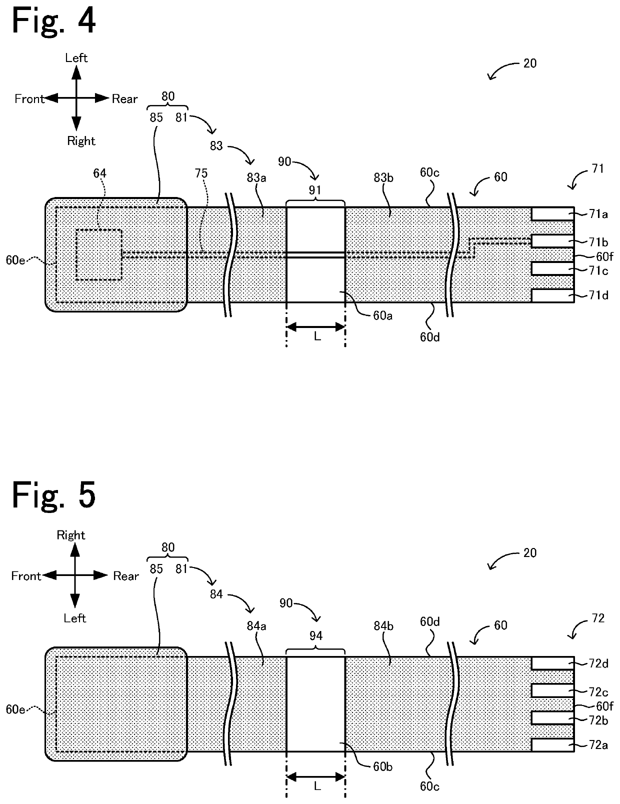
[0084]In Experimental example 2, a gas sensor 10 that was the same as the gas sensor 10 prepared in Experimental example 1 was prepared, except that the shape of the first and second inner porous layers 83 and 84 was changed such that the insulator 44b and the water-penetration reduction portion 90 had the positional relationship illustrated in FIG. 6 in the front-to-rear direction. In Experimental example 2, the first and second water-penetration reduction portions 91 and 94 were included in the insulator 44b in the front-to-rear direction as illustrated in FIG. 6, and the overlap length W was 5 mm (=L). In Experimental example 2, the front ends of the first and second water-penetration reduction portions 91 and 94 were located 31 mm from the front end of the element main body 60.

experimental examples 3 to 5

[0085]In Experimental examples 3 to 5, a gas sensor 10 that was the same as the gas sensor 10 prepared in Experimental example 1 was prepared, except that the shape of the first and second inner porous layers 83 and 84 was changed such that the insulator 44b and the water-penetration reduction portion 90 had the positional relationship illustrated in FIG. 9 in the front-to-rear direction. In Experimental examples 3 to 5, the length L of the first and second water-penetration reduction portions 91 and 94 was set to 5 mm. As illustrated in FIG. 9, the rear end-side parts of the first and second water-penetration reduction portions 91 and 94 overlapped the insulator 44b in the front-to-rear direction, and the overlap length W was 3 mm, 0.5 mm, and 0.3 mm in Experimental examples 3, 4, and 5, respectively. The distance from the front end of the element main body 60 to the front ends of the first and second water-penetration reduction portions 91 and 94 was 27 mm, 24.5 mm, and 24.3 mm in...


PUM


Abstract

A gas sensor includes a sensor element and one or more hollow columnar dense bodies. The sensor element includes an element main body having a side surface, a porous layer and a water-penetration reduction portion that cover at least a front end-side part of the side surface. The water-penetration reduction portion disposed on the side surface so as to divide the porous layer an overlap length W that is the length of a continuous overlap between a range in which the water-penetration reduction portion is present in the longitudinal direction and a range in which inner peripheral surfaces of the one or more dense bodies are present in the longitudinal direction being 0.5 mm or more, the water-penetration reduction portion being a gap region in which the porous layer is absent, the water-penetration reduction portion reduces the capillarity of water.

Description

CROSS-REFERENCE TO RELATED APPLICATION[0001]This application is a continuation application of PCT / JP2019 / 001867, filed on Jan. 22, 2019, which claims the benefit of priority of Japanese Patent Application No. 2018-019446, filed on Feb. 6, 2018, the entire contents of which are incorporated herein by reference.BACKGROUND OF THE INVENTION1. Field of the Invention[0002]The present invention relates to a gas sensor.2. Description of the Related Art[0003]Gas sensors that include a sensor element that detects the concentration of a particular gas, such as NOx, in the measurement-object gas, such as an automotive exhaust gas, are known (e.g., PTLs 1 and 2). The sensor element disclosed in PTL 1 includes a multilayer body that includes oxygen ion-conducting solid electrolyte layers stacked on top of one another. This sensor element also includes an outer pump electrode, a lead wire for the outer pump electrode, a connector electrode, and a porous protection layer, which are stacked on and a...

Claims


Application Information

Patent Timeline
IPC IPC(8): G01N27/407G01N33/00
CPCG01N27/4071G01N33/0036G01N27/4078G01N33/0016G01N27/4077
Inventor NAKAYAMA, YUKIKAGEYAMA, SHOTAFUJII, YUSUKEKOSAKA, KEI
Owner NGK INSULATORS LTD
Why Eureka
Try Eureka