
Lighting device, lighting device element, and processes for the production thereof

Inactive Publication Date: 2020-02-13
SIGNIFY HOLDING B V
View PDF10 Cites 0 Cited by
  • Summary
  • Abstract
  • Description
  • Claims
  • Application Information

AI Technical Summary

Benefits of technology

The patent text describes a need for flexible and low-cost tooling to create a large variety of spot designs in the retail market. This is important because it allows for customization to meet the needs of specific customers, without the need for expensive tooling. The patent describes a lighting device that is flexible in size and shape, performs well in terms of thermal performance, and can be made quickly and inexpensively. This allows for a high level of design freedom, as the lighting device can be custom-made to fit specific areas or even rooms, taking into account their dimensions and other sources of lighting.

Problems solved by technology

This often leads to difficulties when designs require investments for tooling in time and money.
Often this time is not available.
However, this method appears to provide mechanical disadvantages.

Method used


Image

  • Lighting device, lighting device element, and processes for the production thereof
  • Lighting device, lighting device element, and processes for the production thereof
  • Lighting device, lighting device element, and processes for the production thereof

Examples


Embodiment Construction

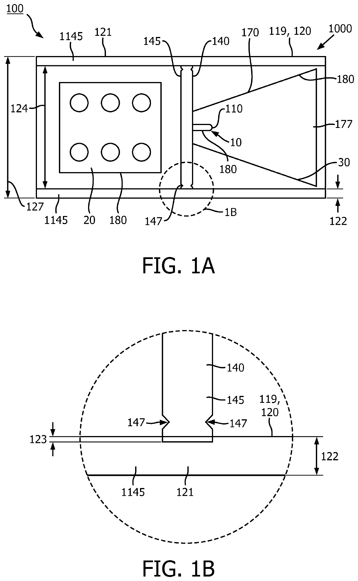
[0138]FIG. 1A schematically depicts some aspects of an embodiment of (the process for production of) the lighting device element 100 and the lighting device 1000. The lighting device element 100 schematically depicted in FIG. 1A, comprises a pipe-like shaped element 120,119, a support 140 and three functional elements 180, i.e., a light source 10, electronics 20 for the light source 10, and optics 30 for the light source 10. The embodiment also schematically depicts a monolithic body 170 providing the support 140 and the optics 30 (for the light source 10). Embodiments of the invention comprise at least two monolithic bodies 170, each monolithic body 170 comprising at least part of the support 140 and at least part of the optics. Together they provide the combined support and optics body 177.

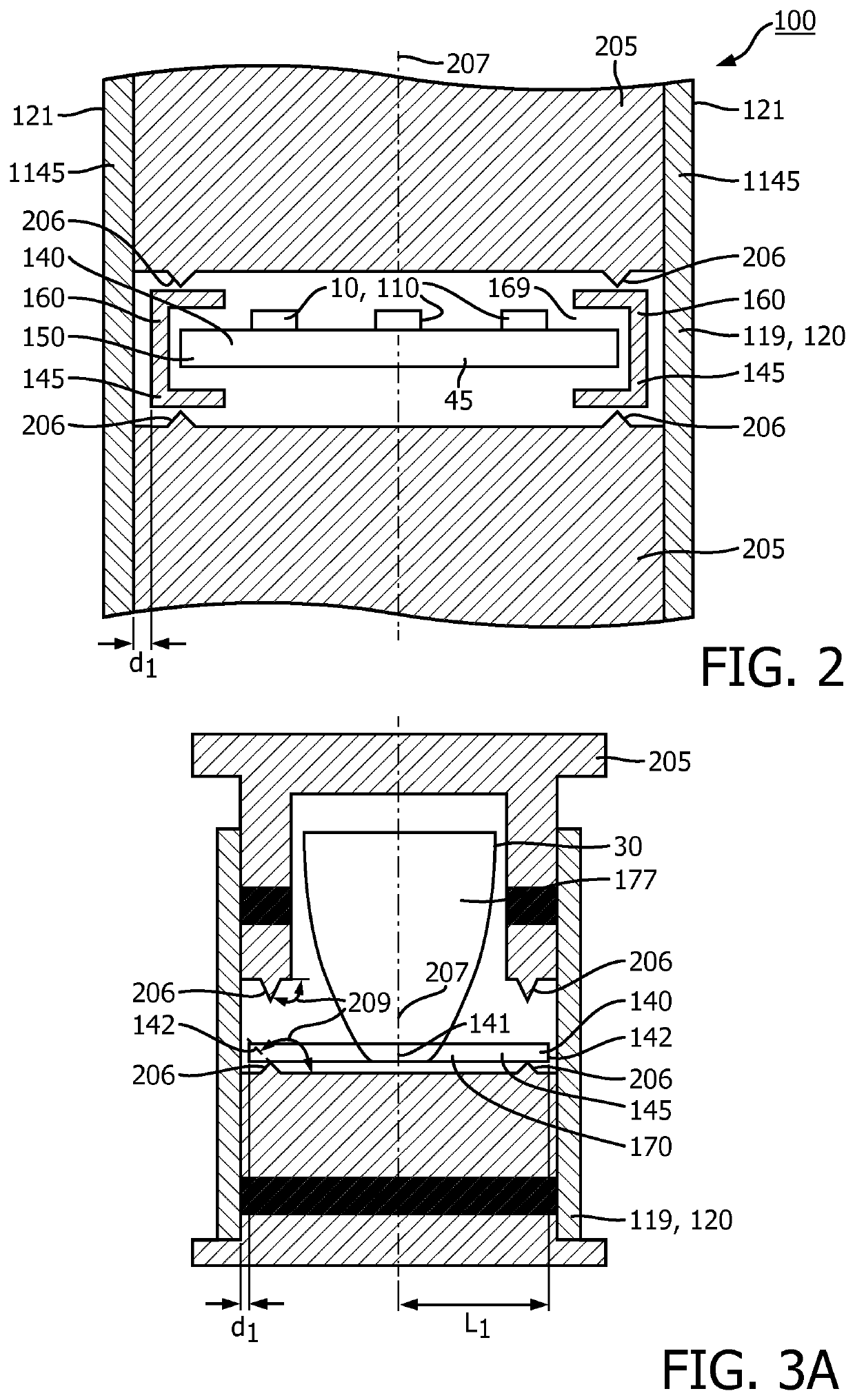
[0139]Other embodiments may comprise a support 140 not provided by at least two monolithic bodies 170. Such embodiments not necessarily comprise optics 30, see e.g. FIG. 2.

[0140]Especially, the ...


PUM


Abstract

The invention provides a lighting device element (100) comprising (i) at least one shaped element (120) selected from the group consisting of a pipe-like shaped element (120,119) and a rod-like shaped element (120,129), (ii) one or more functional elements (180) selected from the group consisting of a light source (10), electronics (20) for a light source (10), a heat sink (1401) and optics (30) for a light source (10), and (iii) a support (140) for the one or more functional element (180), wherein the lighting device element comprises at least said optics as functional element, wherein the lighting device element (100) comprises at least two monolithic bodies (170), each monolithic body (170) comprising at least part of the support (140) and at least part of the optics (30), with said at least two monolithic bodies (170) providing thereby said support (140) and said optics (30), wherein (a1) at least part of the support (140) and (a2) at least part of the one or more functional elements (180) are accommodated within and / or around the shaped element (120); wherein the support (140) and the one or more functional elements (180) are coupled; wherein (b1) the support (140) comprises at least part of a fastening material (145) and / or (b2) a support assist (160), at least partly configured within and / or around the shaped element (120), comprises at least part of the fastening material (145) and the support assist (160) comprises a receptor opening (169) hosting at least part of the support (140); wherein adjacent to a shaped element wall (121) of the shaped element (120) the fastening material (145) comprises (c1) an indentation (147) and (c2) part of the fastening material (145) is in pressed physical contact with said shaped element wall (121) and / or protruding into said shaped element wall (121) via which the support (140) is locally fixed to the shaped element (120).

Description

FIELD OF THE INVENTION[0001]The invention relates to a lighting device and a lighting device element (for such lighting device). The invention further relates to a process for the production of such lighting device element and to a process for the production of such lighting device (comprising such lighting device element).BACKGROUND OF THE INVENTION[0002]Light emitting devices with an adjustable location of the light emitting elements are known in the art. US20080192493, for instance, describes a solid state light emitting apparatus method wherein one or more solid state light emitting elements are mounted on a hardcoat anodized aluminum substrate. One or more bars also may be provided that slidably contact an edge of the hardcoat anodized aluminum substrate. The substrate and the bar(s) may be mounted in a housing with the bars mounted in apertures in the housing wall. Assembling methods for solid state light emitting apparatus also are described.[0003]US 2008 / 0123340 A1, e.g., de...

Claims


Application Information

Patent Timeline
IPC IPC(8): F21V17/10F21V19/02F21V29/71F21V7/22F21V15/01
CPCF21V15/013F21V7/22F21V17/101F21V19/02F21V29/713F21K9/90F21S8/04F21V7/10F21V29/505F21V29/89F21Y2115/10
Inventor DUIJMELINK, ANDREAS ALOYSLUS HENRICUSVERHOEVEN, MARK JOHANNES ANTONIUS
Owner SIGNIFY HOLDING B V
Learn More