Light source unit, and display and lighting device each including same
a technology of light source unit and display, which is applied in the direction of lighting and heating apparatus, instruments, group 3/13 element organic compounds, etc., can solve the problem of difficulty in offering both higher brightness of obtained liquid crystal displays, and achieve enhanced color reproducibility and brightness. high
- Summary
- Abstract
- Description
- Claims
- Application Information
AI Technical Summary
Benefits of technology
Problems solved by technology
Method used
Image
Examples
example 1
[0390]
[0391]Into a 100-ml polyethylene container, 16.0 g of a silicone resin serving as a matrix resin and 8.0 g of Green Phosphor 1 were put and mixed. Subsequently, using a planetary stirring / defoaming device, the resultant mixture was stirred and defoamed at 2,000 rpm for 5 minutes to prepare a phosphor composition.
[0392]
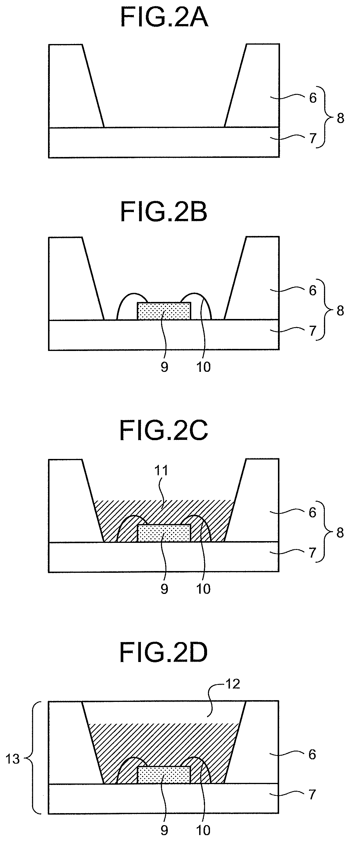
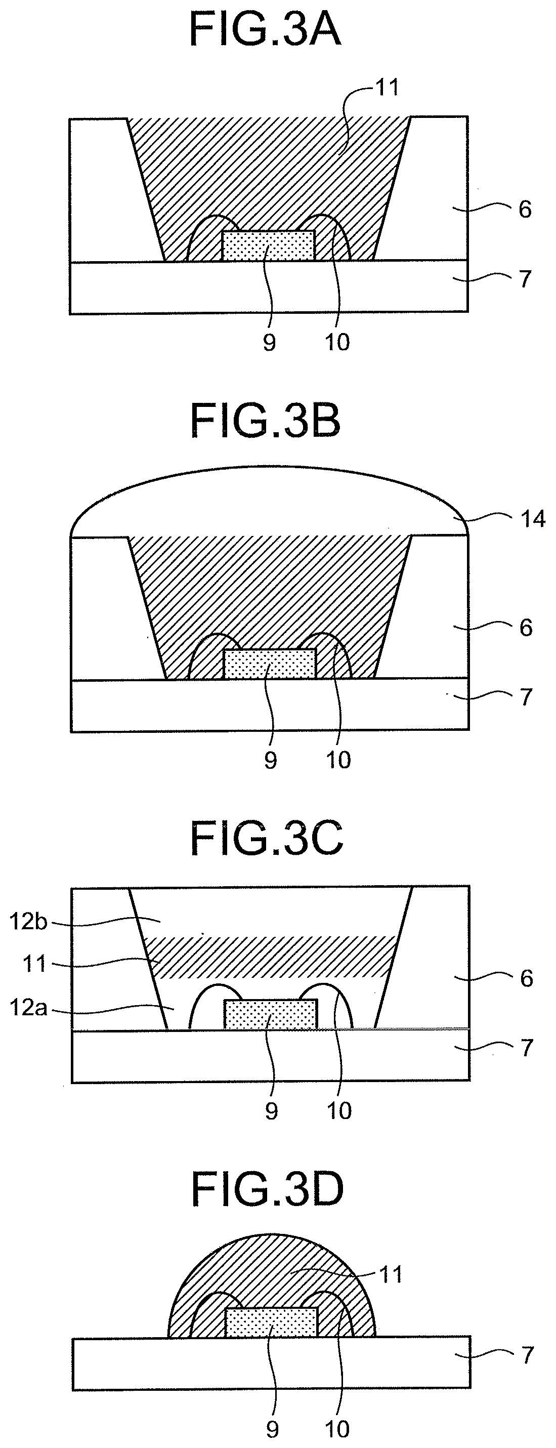
[0393]The obtained phosphor composition was poured into a package frame (a frame “TOP LED BASE”, manufactured by ENOMOTO Co., Ltd.) mounted with an LED chip (“GM2QT450G”, manufactured by Showa Denko K.K. average wavelength: 454 nm) by using a dispenser (“MPP-1”, manufactured by Musashino Engineering, Inc.), and cured at 80° C. for 1 hour and then cured at 150° C. for 2 hours to prepare a light emitting body.
[0394]
[0395]As a binder resin, a polyester resin (SP value=10.7 (cal / cm3)0.5) was used. 0.017 part by weight of the compound R-1 as an organic luminescent material and 300 parts by weight of toluene as a solvent were mixed with 100 parts by weight of the binde...
example 2
[0399]
[0400]As the thermoplastic resin X, polyethylene terephthalate (PET) having a melting point of 258° C. was used. As the thermoplastic resin Y, ethylene terephthalate (PE / SPG⋅T / CHDC) that is a noncrystalline resin having no melting point and obtained by copolymerizing 25-mol % spiroglycol and 30-mol % cyclohexanedicarboxylic acid was used.
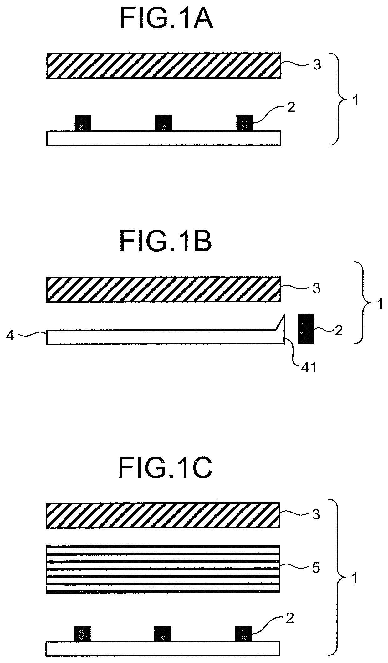
[0401]The prepared crystalline polyester and thermoplastic resin Y were fed into two single-shaft extruders, respectively, and melted at 280° C. and kneaded. Next, the resultant crystalline polyester and the resultant thermoplastic resin Y were each passed through five FSS leaf disc filters, and then, while being weighed using a gear pump, flows of the resins were joined at a lamination device having eleven slits to form a laminate in which eleven layers were alternately laminated in the thickness direction. The method of forming the laminate was conducted as described in paragraphs [0053] to [0056] in Patent Literature 6. Here, the lengths of...
example 3
[0406]A laminated film, a color conversion film, and a laminated member were obtained in the same manner as in Example 2, except that the number of layers X made of the thermoplastic resin X was 101, and the number of layers Y made of the thermoplastic resin Y was 100.
[0407]Table 4 lists evaluation results of the laminated member in Example 3 and a light source unit including this laminated member. Table 4 reveals that Example 3 was higher in brightness than Example 2 in which the number of the layers was smaller. Example 3 was equivalent in color gamut area to Example 1.
PUM
 Abstract
Description
Claims
Application Information
 - R&D
- Intellectual Property
- Life Sciences
- Materials
- Tech Scout
- Unparalleled Data Quality
- Higher Quality Content
- 60% Fewer Hallucinations
Browse by: Latest US Patents, China's latest patents, Technical Efficacy Thesaurus, Application Domain, Technology Topic, Popular Technical Reports.
© 2025 PatSnap. All rights reserved.Legal|Privacy policy|Modern Slavery Act Transparency Statement|Sitemap|About US| Contact US: help@patsnap.com


