
Vehicular speaker temperature control device, control method thereof, and vehicle including device

a technology for controlling devices and vehicular speakers, applied in temperatue control, process and machine control, instruments, etc., can solve problems such as reducing affecting the performance of vehicular speakers, and deteriorating low-band sound quality of vehicular speakers, so as to ensure the performance and reliability of speakers

Active Publication Date: 2020-02-06
HYUNDAI MOTOR CO LTD +1
View PDF3 Cites 5 Cited by
  • Summary
  • Abstract
  • Description
  • Claims
  • Application Information

AI Technical Summary

Benefits of technology

The present invention relates to a device, method, and vehicle for controlling the temperature of a speaker in a vehicle to ensure its performance and reliability. The device applies a driving signal with a specific frequency to the speaker unit when the internal temperature of the vehicle or the speaker is below a preset reference temperature. This driving signal increases the temperature of the speaker unit, ensuring its performance and reliability. The device also measures the current temperature of the vehicle and applies the driving signal only when the temperature is within a certain range to minimize power consumption. The control speed is increased by using an information table that maps driving frequencies to temperature differences, and the temperature control time is minimized. Additionally, the device prevents the driving signal from being applied when the current temperature of the vehicle is greater than the preset reference temperature.

Problems solved by technology

However, in contrast with a general home speaker, vehicular speakers may be significantly affected by the environment and space in which the vehicle is positioned.
In particular, the low-band sound quality of vehicular speakers often deteriorates at low temperatures (e.g., −5° C. or less).
As such, increase in the numerical values of the lowest resonance frequency and the Q-factor due to the hardening of the edge and the damper has been identified as a major cause for reduction in performance of vehicular speakers.

Method used


Image

  • Vehicular speaker temperature control device, control method thereof, and vehicle including device
  • Vehicular speaker temperature control device, control method thereof, and vehicle including device
  • Vehicular speaker temperature control device, control method thereof, and vehicle including device

Examples


first embodiment

[0150]FIG. 9 is a flowchart for explanation of a method of controlling vehicular speaker temperature according to the present disclosure. FIG. 10 is a diagram showing a driving signal information table according to the embodiment of FIG. 9.

[0151]As shown in FIGS. 9 and 10, a vehicular speaker temperature control device according to the present disclosure may first detect opening and closing states of a vehicular door (S100).

[0152]Then, when the vehicular door is in the opening state, the vehicular speaker temperature control device may measure current internal temperature of the vehicle (S110).

[0153]Then, the vehicular speaker temperature control device may determine whether the measured current internal temperature of the vehicle is less than or equal to preset reference temperature (S120).

[0154]Here, the reference temperature may be room temperature and, in this case, the room temperature may be any one temperature in the range of about 10 degrees to about 30 degrees but is not li...

second embodiment

[0169]FIG. 11 is a flowchart for explanation of a method of controlling vehicular speaker temperature according to the present disclosure.

[0170]As shown in FIG. 11, the vehicular speaker temperature control device according to the present disclosure may first detect opening and closing states of a vehicular door (S200).

[0171]Then, when the vehicular door is in the opening state, the vehicular speaker temperature control device may measure internal temperature of the speaker unit (S210).

[0172]Then, the vehicular speaker temperature control device may determine whether the measured internal temperature of the speaker unit is less than or equal to the preset reference temperature (S220).

[0173]Here, the reference temperature may be room temperature and, in this case, the room temperature may be any one temperature in the range of about 10 degrees to about 30 degrees but is not limited thereto.

[0174]In addition, when the measured current internal temperature of the speaker unit is less t...

third embodiment

[0183]FIG. 12 is a flowchart for explanation of a method of controlling vehicular speaker temperature according to the present disclosure.

[0184]As shown in FIG. 12, the vehicular speaker temperature control device according to the present disclosure may first detect opening and closing states of a vehicular door (S300).

[0185]Then, when the vehicular door is in the opening state, the vehicular speaker temperature control device may measure internal temperature of the vehicle (S310).

[0186]Then, the vehicular speaker temperature control device may determine whether the measured internal temperature of the vehicle is less than or equal to the preset reference temperature (S320).

[0187]In addition, when the measured current internal temperature of the vehicle is less than or equal to the preset reference temperature, the vehicular speaker temperature control device may apply a driving signal of a specific frequency to the speaker unit (S330) to increase the temperature of the speaker unit...


PUM


Abstract

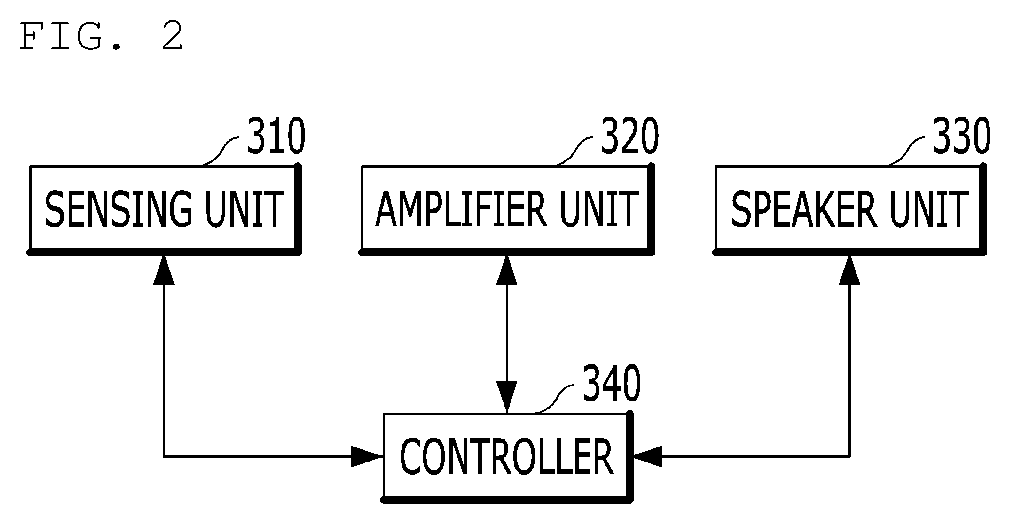
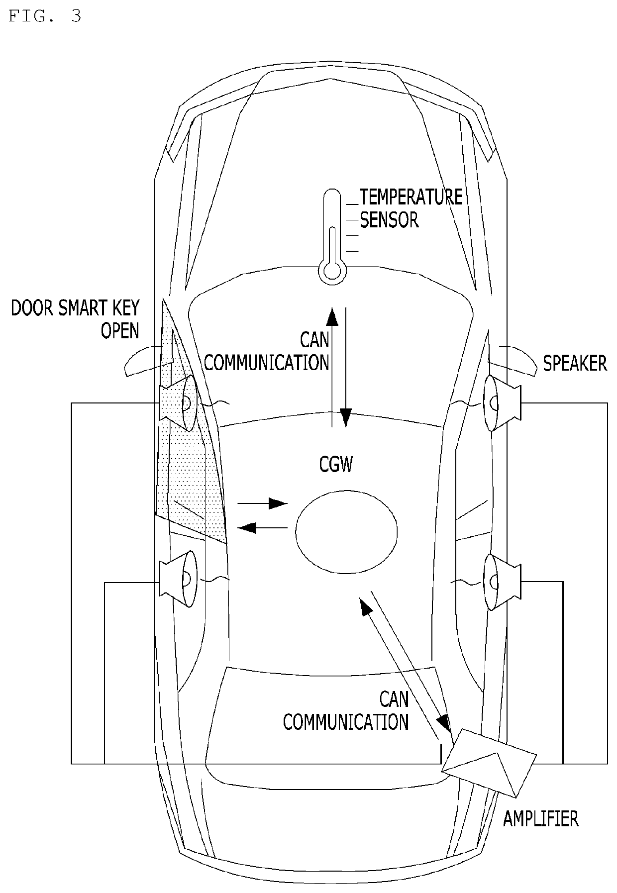
A vehicular speaker temperature control device may include: a sensing unit configured to sense a temperature of a vehicle; an amplifier unit configured to amplify a sound of the vehicle; a speaker unit connected to the amplifier unit and configured to output the amplified sound; and a controller in operable communication with the sensing unit and the amplifier unit. The controller may receive a current temperature of the vehicle measured by the sensing unit, to determine whether the current temperature of the vehicle is less than or equal to a preset reference temperature, and when the current temperature of the vehicle is less than or equal to the preset reference temperature, to control operation of the amplifier unit so as to cause an increase in temperature of the speaker unit by applying a driving signal of a specific frequency to the speaker unit.

Description

CROSS-REFERENCE TO RELATED APPLICATION[0001]This application claims the benefit of priority to Korean Patent Application No. 10-2018-0091160, filed on Aug. 6, 2018 in the Korean Intellectual Property Office, the entire contents of which are hereby incorporated by reference as if fully set forth herein.BACKGROUND OF THE DISCLOSURETechnical Field[0002]The present disclosure relates to a vehicular speaker temperature control device, and more particularly, to a vehicular speaker temperature control device, a control method thereof, and a vehicle including the vehicular speaker temperature control device.Discussion of the Related Art[0003]In general, a vehicle multimedia system, such as an audio system, a car stereo system, or a navigation device, is capable of outputting sound through a speaker installed in the vehicle. The speaker may include a unit for reproducing sound, which may be classified into various unit types such as a low / high-note unit (2 ways) for reproducing low and high ...

Claims


Application Information

Patent Timeline
Patent Type & Authority Applications(United States)
IPC IPC(8): B60H1/00H04R3/00H04R29/00
CPCH04R3/007H04R29/001B60H1/00735H04R2499/13H04R3/00G05D23/20H04R2430/00
Inventor HWANG, YONG HWAN
Owner HYUNDAI MOTOR CO LTD
Learn More