
Machine-tool-state determination system and machine-tool-state determination method

Active Publication Date: 2020-01-23
HITACHI LTD
View PDF0 Cites 5 Cited by
  • Summary
  • Abstract
  • Description
  • Claims
  • Application Information

AI Technical Summary

Benefits of technology

The goal of the patent is to create a system and method that can accurately understand the status of a machine tool. This helps to identify issues with the machine and take appropriate measures to fix them.

Problems solved by technology

The method disclosed in International Publication No. 2013 / 031353 is incapable of classifying a type of abnormality.
As a result, there may also be a disadvantage an evaluations as described above comes at a high cost.
That is, the conventional technique art is difficult to accurately grasp a state associated with the machine tool.

Method used


Image

  • Machine-tool-state determination system and machine-tool-state determination method
  • Machine-tool-state determination system and machine-tool-state determination method
  • Machine-tool-state determination system and machine-tool-state determination method

Examples


first embodiment

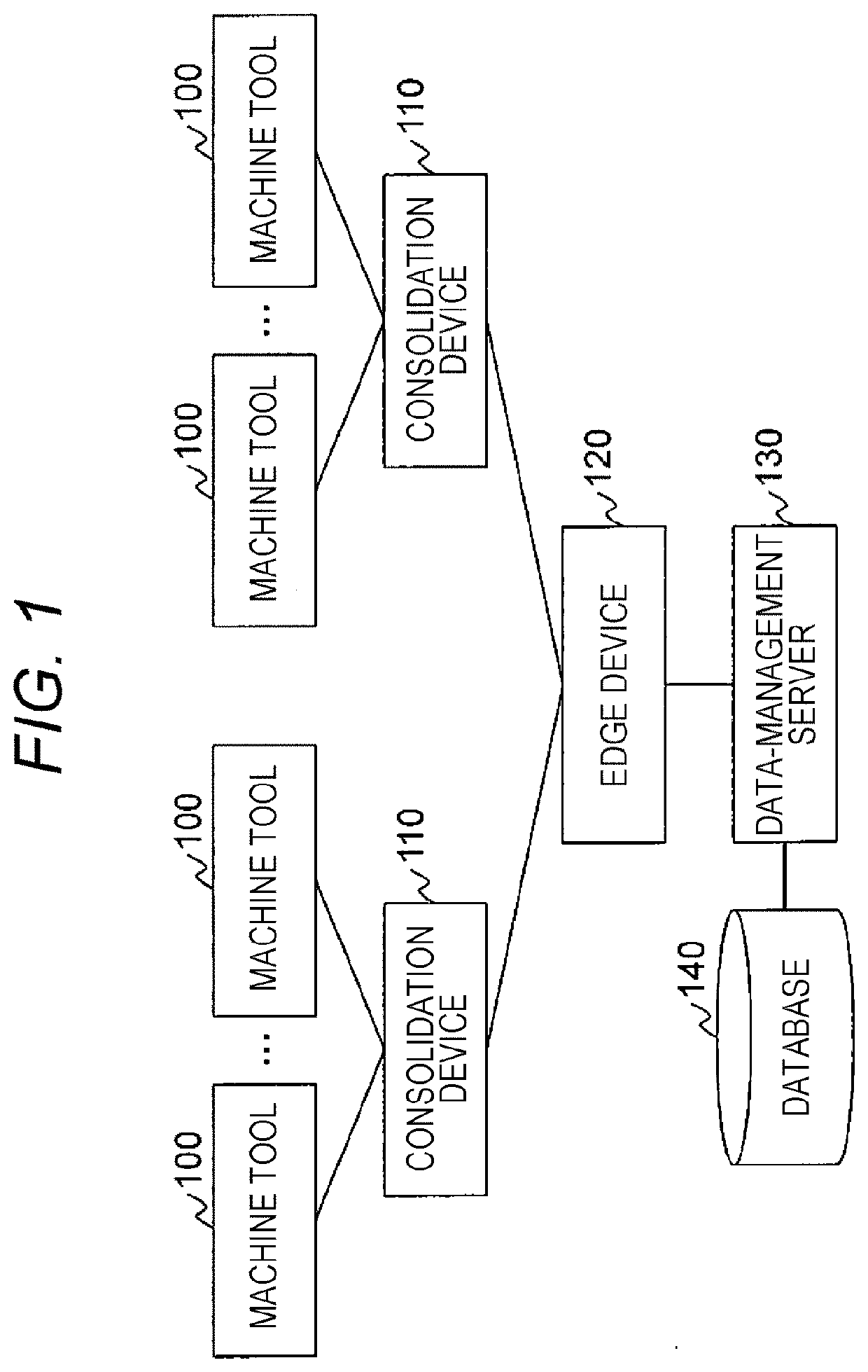
[0033]FIG. 1 is an illustration of an exemplary configuration of a system according to a first embodiment.

[0034]The system includes a plurality of machine tools 100, a plurality of consolidation devices 110, an edge device 120, a data-management server 130, and a database 140.

[0035]The plurality of machine tools 100 is connected, directly or through a network, to the plurality of the consolidation devices 110, respectively. Each of the plurality of consolidation devices 110 connects to the edge device 120 directly or through a network. The edge device 120 connects to the data-management server 130 directly or through a network. The data-management server 130 connects to the database 140 directly or through a network.

[0036]Note that the present invention is not limited to the type of network. Examples of the network include a local area network (LAN) and a wide area network (WAN). In addition, the connection method of the network may be either wired or wireless.

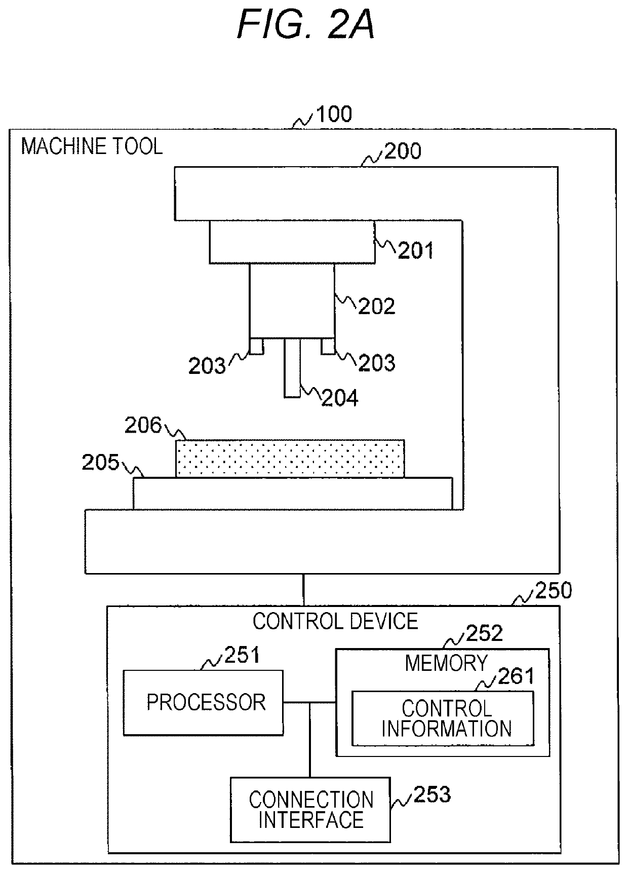
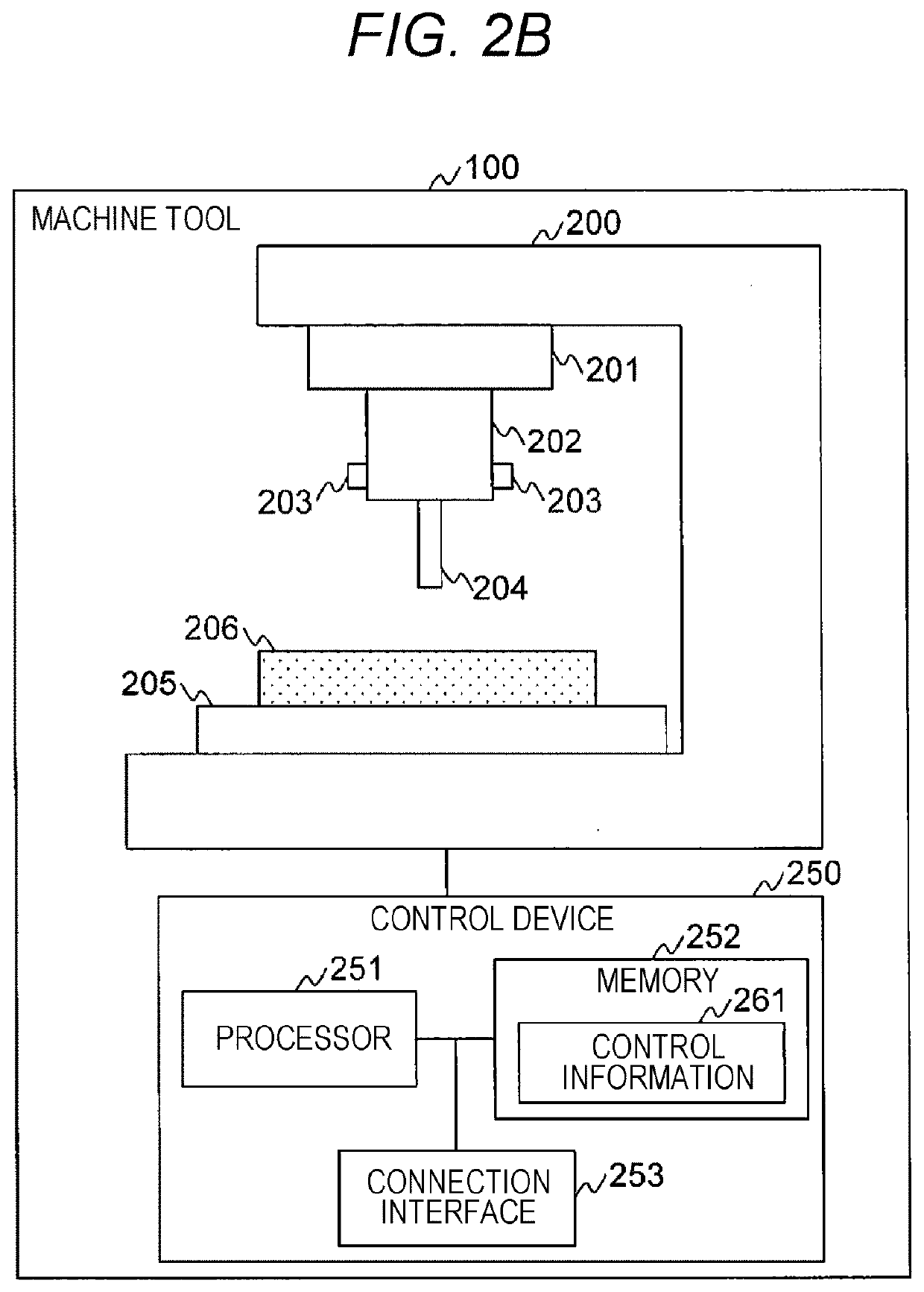
[0037]Each of the mach...


PUM


Abstract

A machine-tool-state determination system configured to determine a state associated with a machine tool including a rotation mechanism for processing a member, the system including: a sensor configured to acquire a state value from the machine tool; and an analysis device, in which the analysis device: performs spectral analysis with time series data of the state value, to extract a rotational frequency of the rotation mechanism and a harmonic wave to the rotational frequency; calculates a ratio of an amplitude of the rotational frequency to an amplitude of the harmonic wave; generates feature-amount data including the state value and the ratio as feature amounts; performs clustering with the feature-amount data; and determines a state associated with the machine tool, based on a result of the clustering.

Description

CLAIM OF PRIORITY[0001]The present application claims priority from Japanese patent application JP 2018-134608 filed on Jul. 18, 2018, the content of which is hereby incorporated by reference into this application.BACKGROUND OF THE INVENTION1. Field of the Invention[0002]The present invention relates to a method of determining a state of a machine tool provided with a rotation mechanism.2. Description of the Related Art[0003]A machine tool that processes a member such as metal includes a rotation mechanism such as a motor, and has a plurality of cutting blades. For example, a rotary tool having a plurality of blades is attached to the rotation mechanism.[0004]Occurrence of abnormality such as machine vibration, blade wear, blade chipping, and blade breakage during a machining operation degrades the quality of a product produced from the member. Thus, there is a demand for a technique of quickly detecting occurrence of an abnormality or predicting an abnormality. For such a demand, t...

Claims


Application Information

Patent Timeline
IPC IPC(8): G05B19/418G06N20/00G06K9/62
CPCG05B19/4184G06N20/00G06K9/6218G05B19/4183G05B19/406G05B2219/31455G05B2219/34465G05B23/024G06V2201/06G06F2218/08G06F18/23
Inventor OTSU, KENJIWATANABE, KEIJIMATSUMOTO, HISANORI
Owner HITACHI LTD
Learn More