
Ground fault detection device

Active Publication Date: 2020-10-08
YAZAKI CORP
View PDF0 Cites 1 Cited by
  • Summary
  • Abstract
  • Description
  • Claims
  • Application Information

AI Technical Summary

Benefits of technology

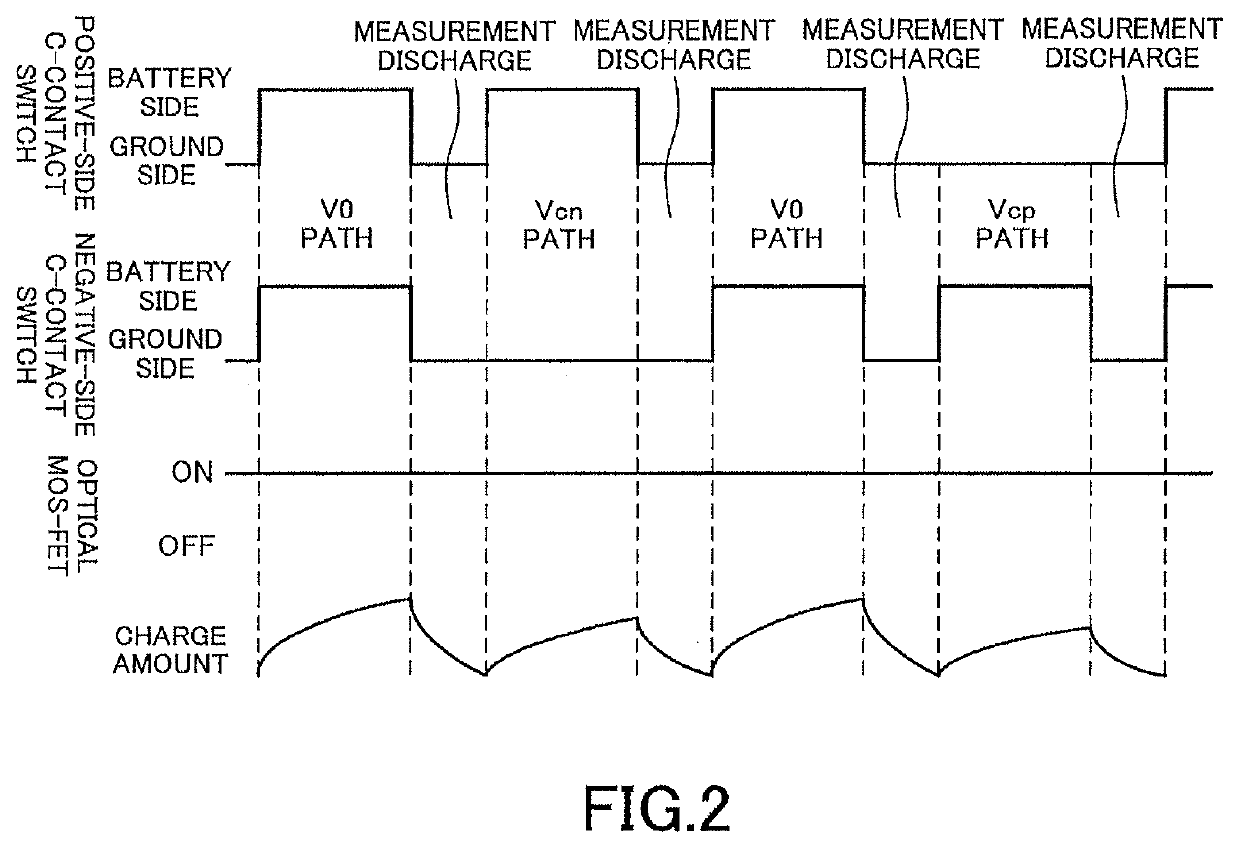
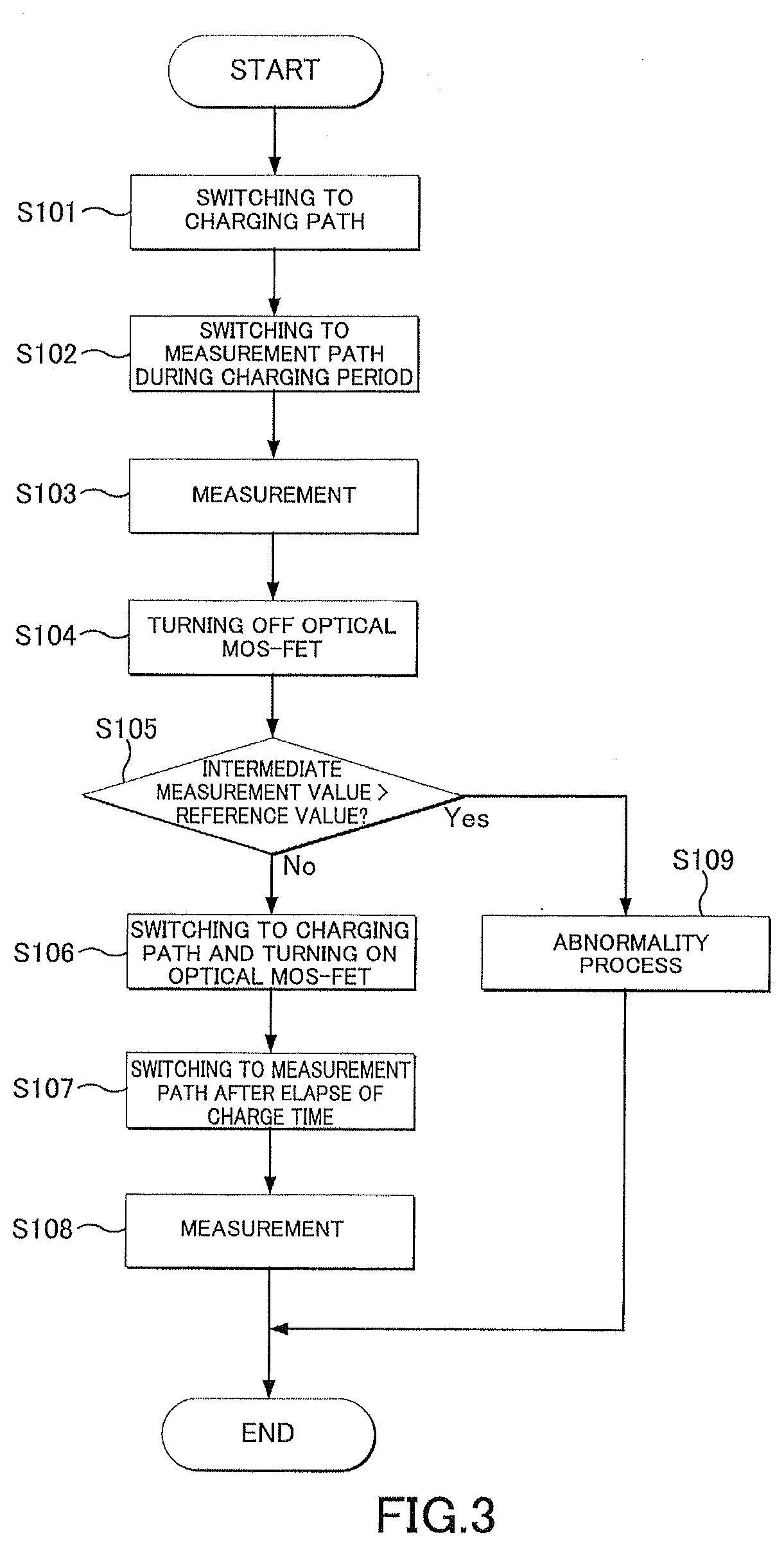
The patent text describes a ground fault detection device that uses a C-contact switch for measuring voltage. The device has a detection capacitor that is connected to either a battery or ground, so it cannot stop charging while holding the charge. The device uses an intermediate measurement to measure the charging voltage during the original charging time. If the measurement value exceeds a reference value due to a decrease in insulation resistance, further charging can be canceled to avoid unnecessary high voltage application, and the ground fault can be early detected. The device can distinguish between an insulation failure and a specific condition of the system by measuring the charge amount of the detection capacitor. The invention provides a cost-effective and reliable ground fault detection device.

Problems solved by technology

Thus, it is not possible to temporarily stop charging while holding the charge.
The C-contact switch is cheaper than the optical MOS-FET, but the reaction speed is on the other hand slower.
For this reason, the ground fault detection device 500 using the C-contact switch temporarily is not suitable for the process of stopping charging and restarting charging after measuring.

Method used


Image

  • Ground fault detection device
  • Ground fault detection device
  • Ground fault detection device

Examples


Embodiment Construction

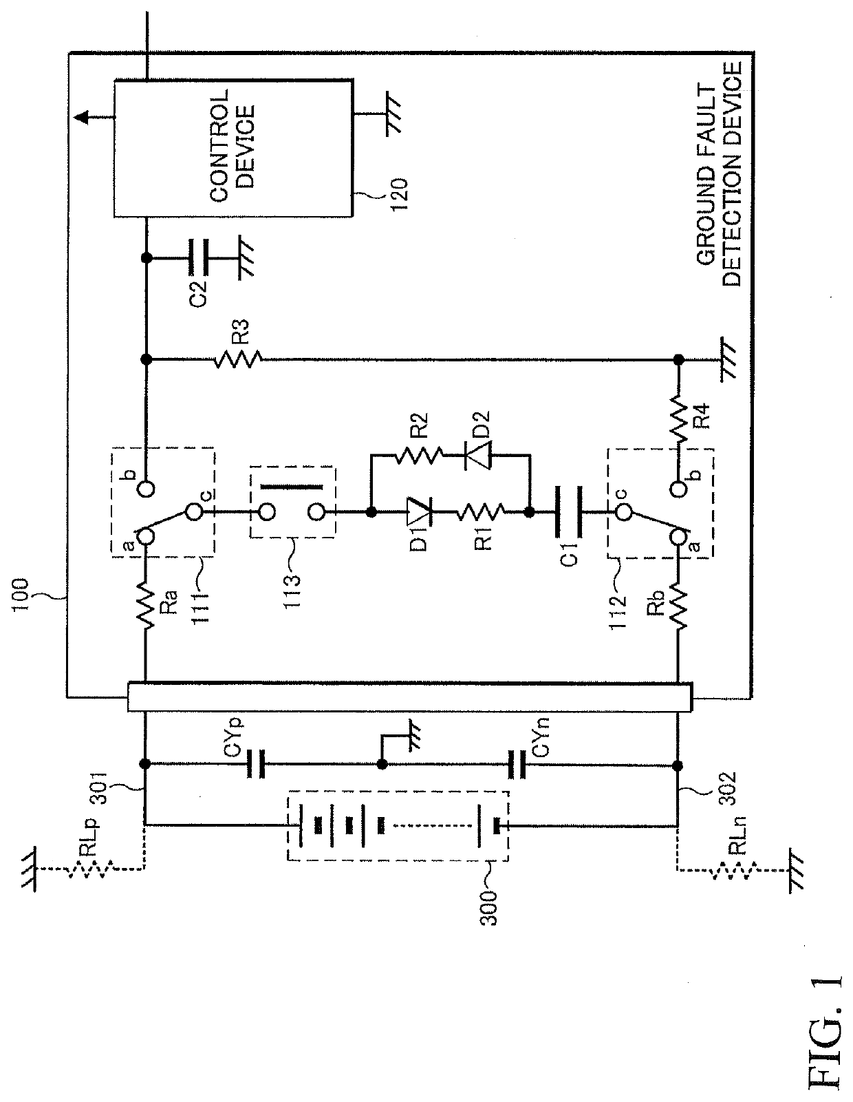
[0039]An embodiment of the present invention will be described in detail with reference to the drawings. FIG. 1 is a block diagram showing a structure of a ground fault detection device 100 which is related to an embodiment of the present invention. The ground fault detection 100 as shown in this figure is a flying capacitor type device that detects a ground fault of the system connected to an ungrounded high voltage battery 300, and in which the high voltage battery 300 is provided. The ground fault detection device 100 is controlled by an external control device that is a host device (not shown).

[0040]Here, an insulation resistance between a positive electrode side of the high voltage battery 300 and the ground is expressed as RLp, and an insulation resistance between a negative electrode side and the ground as RLn. High voltage means higher one than a low voltage battery (typically 12V) for driving various devices in a vehicle (lamp, wiper), and the high voltage battery 300 is a ...


PUM


Abstract

A ground fault detection device that is connected to an ungrounded battery, estimates an insulation resistance of the system provided with the battery, and detects a ground fault, includes a capacitor that operates as a flying capacitor, two C-contact switches that switch a V0 charging path including the battery and the capacitor, a Vcn charging path including the battery, a negative-side insulation resistance that is an insulation resistance between a negative side of the battery and ground, and the capacitor, a Vcp charging path including the battery, a positive-side insulation resistance insulation resistance that is an insulation resistance between a positive-side insulation resistance of the battery and ground, and the capacitor, and a measurement path that serves both a charge voltage measurement and a discharge of the first capacitor, and an optical MOS-FET capable of blocking charge inflow to and charge outflow from the capacitor.

Description

BACKGROUND OF THE INVENTIONField of the Invention[0001]The present invention relates to a ground fault detection device using a flying capacitor.Description of the Related Art[0002]In a hybrid car equipped with an engine and an electric motor as drive sources, and electric cars, a battery mounted on a vehicle body is charged and driving force is generated using an electric energy supplied from the battery. Generally, battery-related power circuit is configured as a high voltage circuit that handles high voltages of 200V or more, and the high voltage circuit has an ungrounded configuration that is electrically insulated from the vehicle body serving as a ground reference potential point for ensuring safety.[0003]In a vehicle equipped with an ungrounded high voltage battery, a ground fault detection device is provided for monitoring an insulation state (ground fault) between a system with a high voltage battery, specifically a main power system from the high voltage battery to the mot...

Claims


Application Information

Patent Timeline
IPC IPC(8): G01R31/52
CPCG01R31/52
Inventor KAWAMURA, YOSHIHIRO
Owner YAZAKI CORP
Learn More